Physical demonstration link on Bilibili: https://www.bilibili.com/video/BV1B94y1n7G7
Foreword: 1. For detailed technical documentation, please refer to the official documentation of "Hardwood Classroom" - Simple Oscilloscope (yuque.com); 2. Capacitors C27, C28, C29, and C30 may cause inaccurate peak-to-peak value measurements, and it is recommended not to solder them;
I. Project Description
This is an oscilloscope + signal source analog front-end expansion board used with the H750 core board. Its main functions and characteristics:
1. Analog input section
: Number of channels: Synchronous dual-channel
Sampling rate/bandwidth: 2MSPS/100KHz
Input range: ±10mV - ±15V
Input impedance: 1MΩ
2. Analog output section
: Number of channels: 1
Output signal waveform types: Sine wave, square wave, triangle wave
Output sine wave frequency: 1Hz - 20KHz
Output range: ±10mV - ±10V
Output impedance: 50 ohms
Output current capability: ±10mA
II. Power supply section
1. Type C interface
Type C interface basics: USB Type C interface pin details - Zhihu (zhihu.com)
16P Type C power supply wiring (6P Type C is recommended for power supply only)
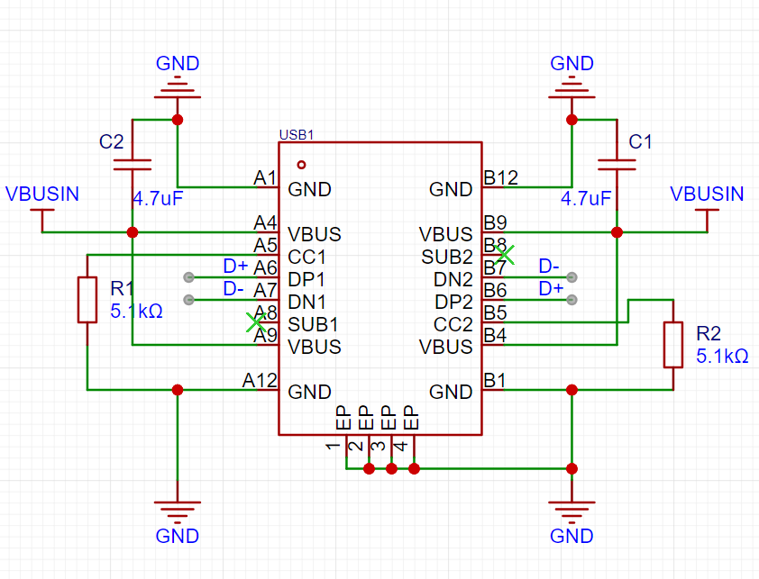

Figure 2.1 Type C power supply wiring diagram
Figure 2.2 Encoder wiring diagram
Note: 1. VBUS must be grounded through a capacitor (filtering); 2. When CC1/2 is not used, it must be grounded through a 5.1kΩ resistor;
2. Power supply module

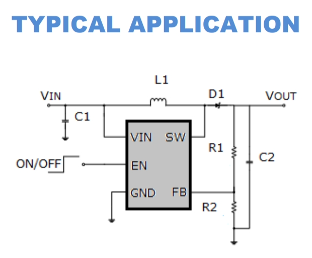
Figure 2-3 Power supply module schematic diagram
Figure 2-4 MT3608 Typical Application Circuit
Notes: MT3608 detailed technical documentation: MT3608.pdf (szlcsc.com) //or MT3608L (can be used as a substitute in this example): MT3608L.pdf (szlcsc.com)
3. The encoder
is shown in Figure 2.2. Hardwood Classroom Encoder Debugging Tutorial: Chapter 4 Changing the Vertical and Horizontal Axes (yuque.com)
III. Important Display Section

(White Screen Display): My personal project progress was delayed for a long time due to the screen section. The main problem was that the screen displayed a white screen. The Hardwood Classroom official documentation also has detailed test steps in this section. Please refer to the LCD test section in Chapter 2, Fast Refresh (yuque.com). It is recommended to directly measure the waveform of the pins of the screen socket to prevent problems caused by poor soldering or contact. Under normal circumstances, the output of the core board will not have problems.
Figure 3.1 Schematic diagram of the 2.8-inch display screen welding circuit.
IV. Input/Output Section.
The official engineering documentation for this section is very detailed. As a novice, I won't presume to explain further here. Please refer to the open-source platforms: [Hardwood Classroom] AFE03 Oscilloscope Signal Source Expansion Board - JLCPCB EDA Open Source Hardware Platform (oshwhub.com); Hardwood Classroom: Hardware Design (yuque.com).


 京公网安备 11010802033920号

 1N5253C(DO-35)-BP


