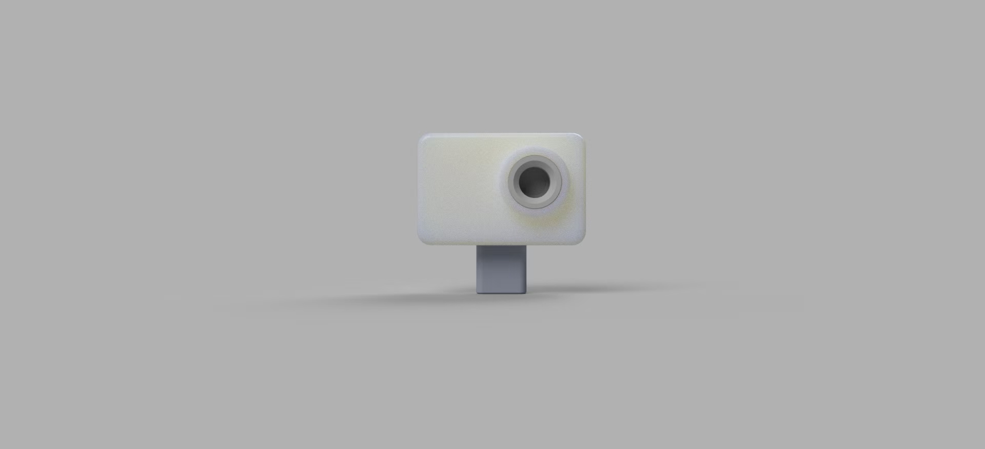
 3D Structure
 and Physical Display.
 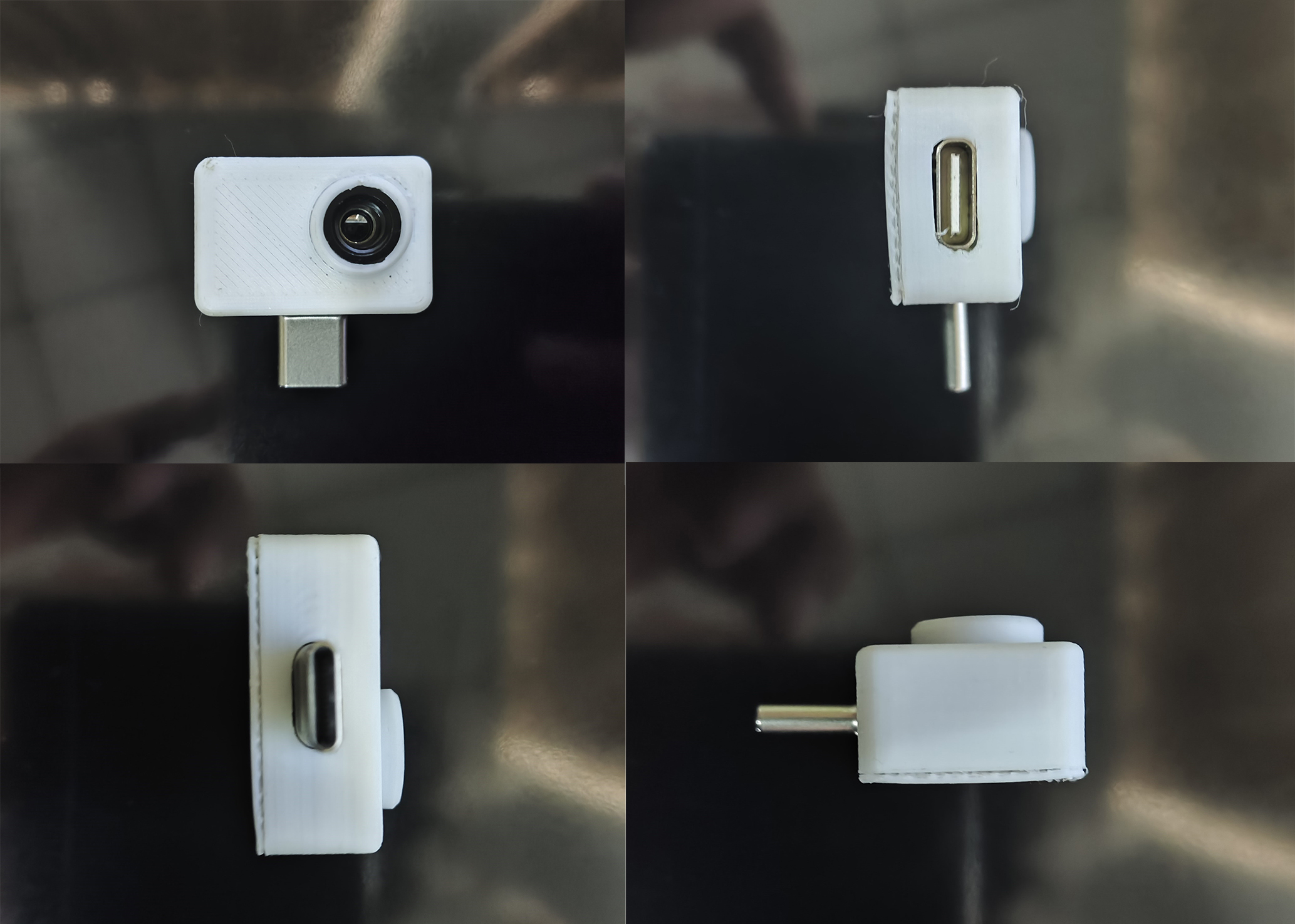 Step 1: Direct Insertion and Connection
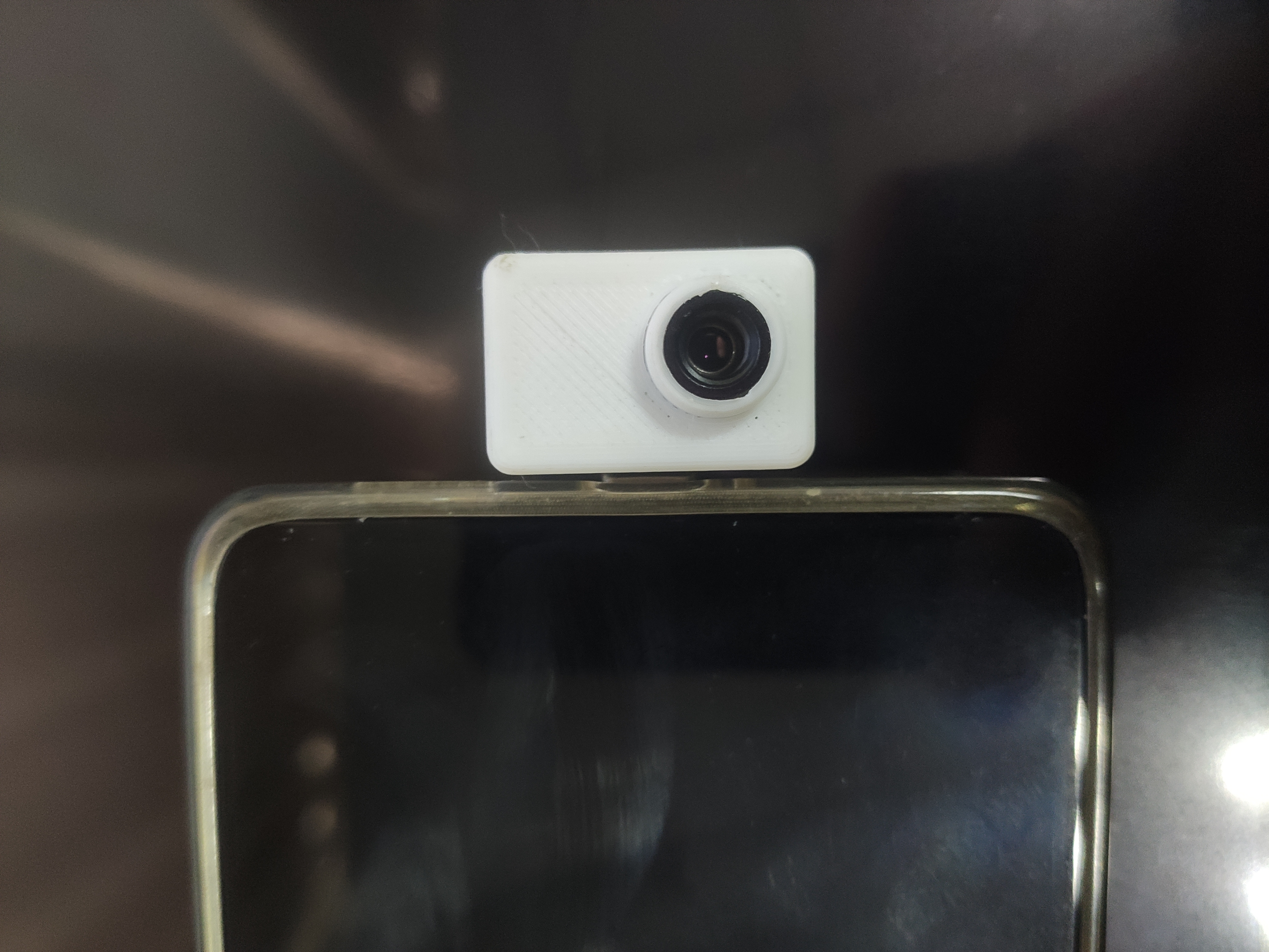
 Function Demonstration.
 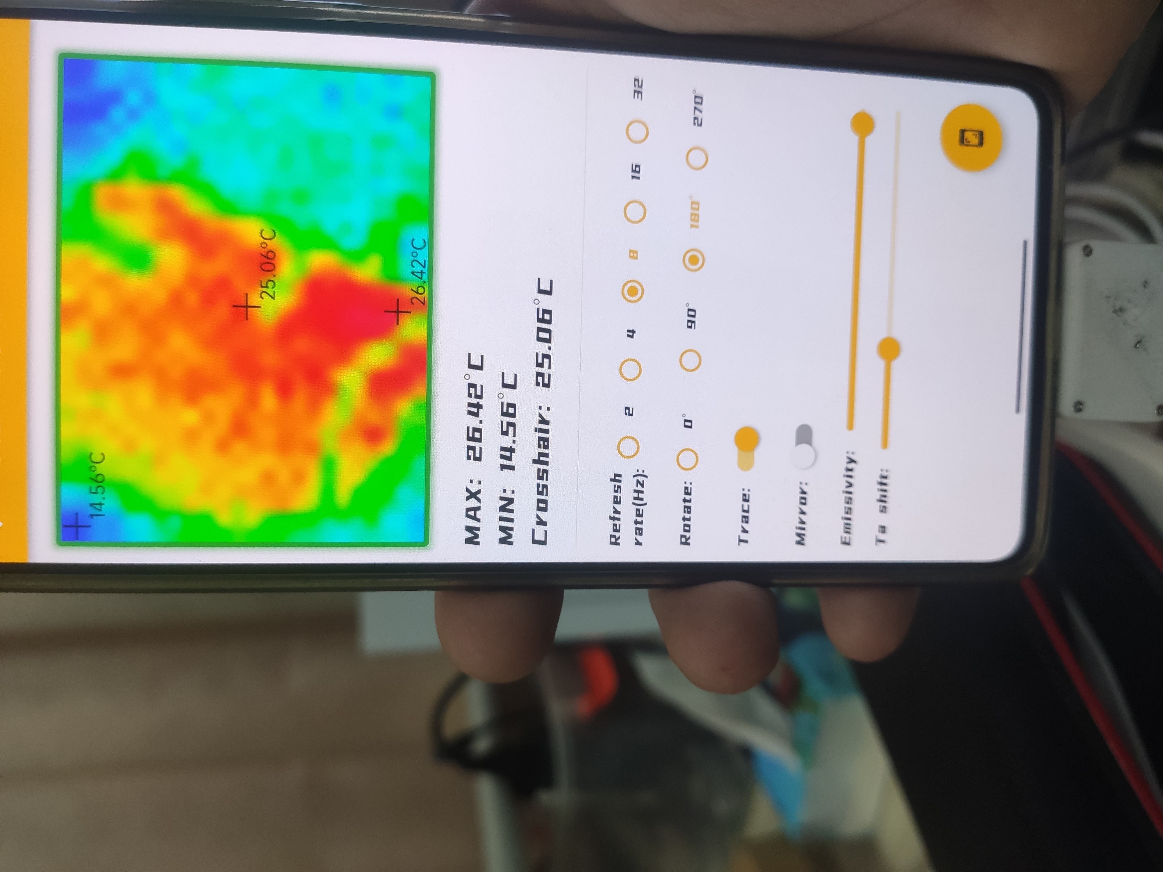 Tutorial:
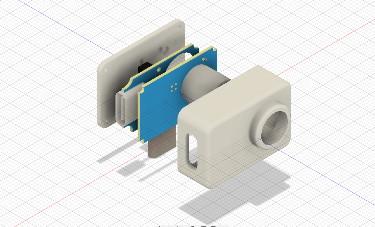
 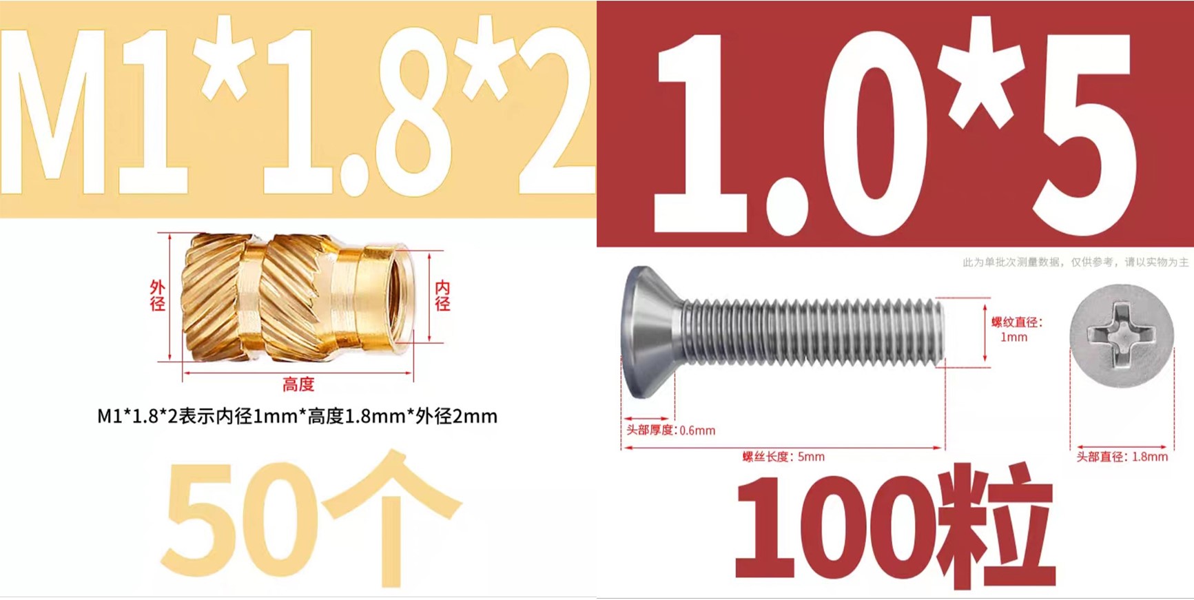 Solder the components according to the PCB (do not solder the CC2 resistor and header pins here), and burn the firmware into it. The pull-down resistor on the left side does not need to be soldered!
 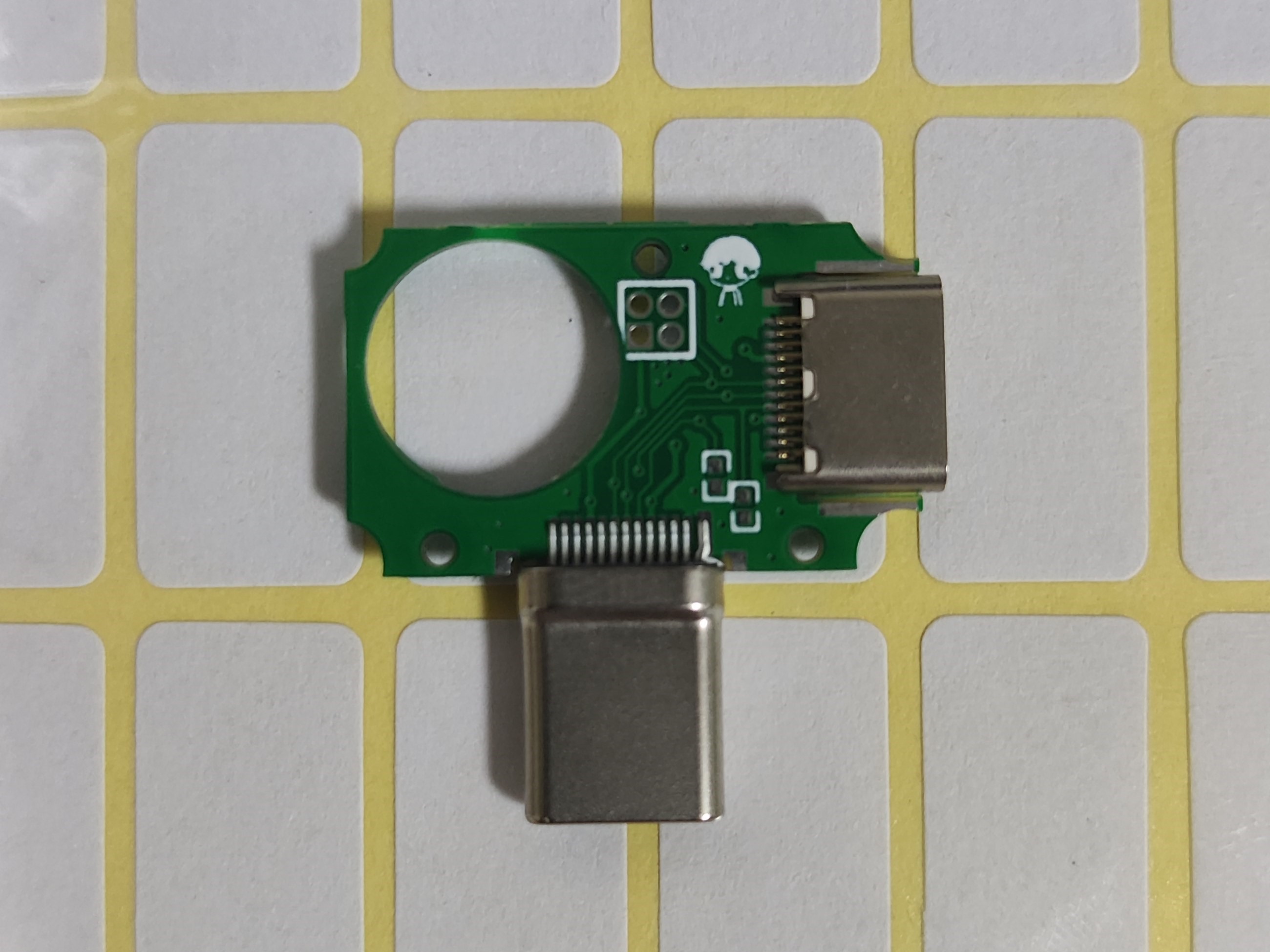 Inject the T-shaped nut into the 3D shell. You can use a soldering iron here, set the temperature to about 120℃, and carefully inject the nut into the 3D shell (care is required).
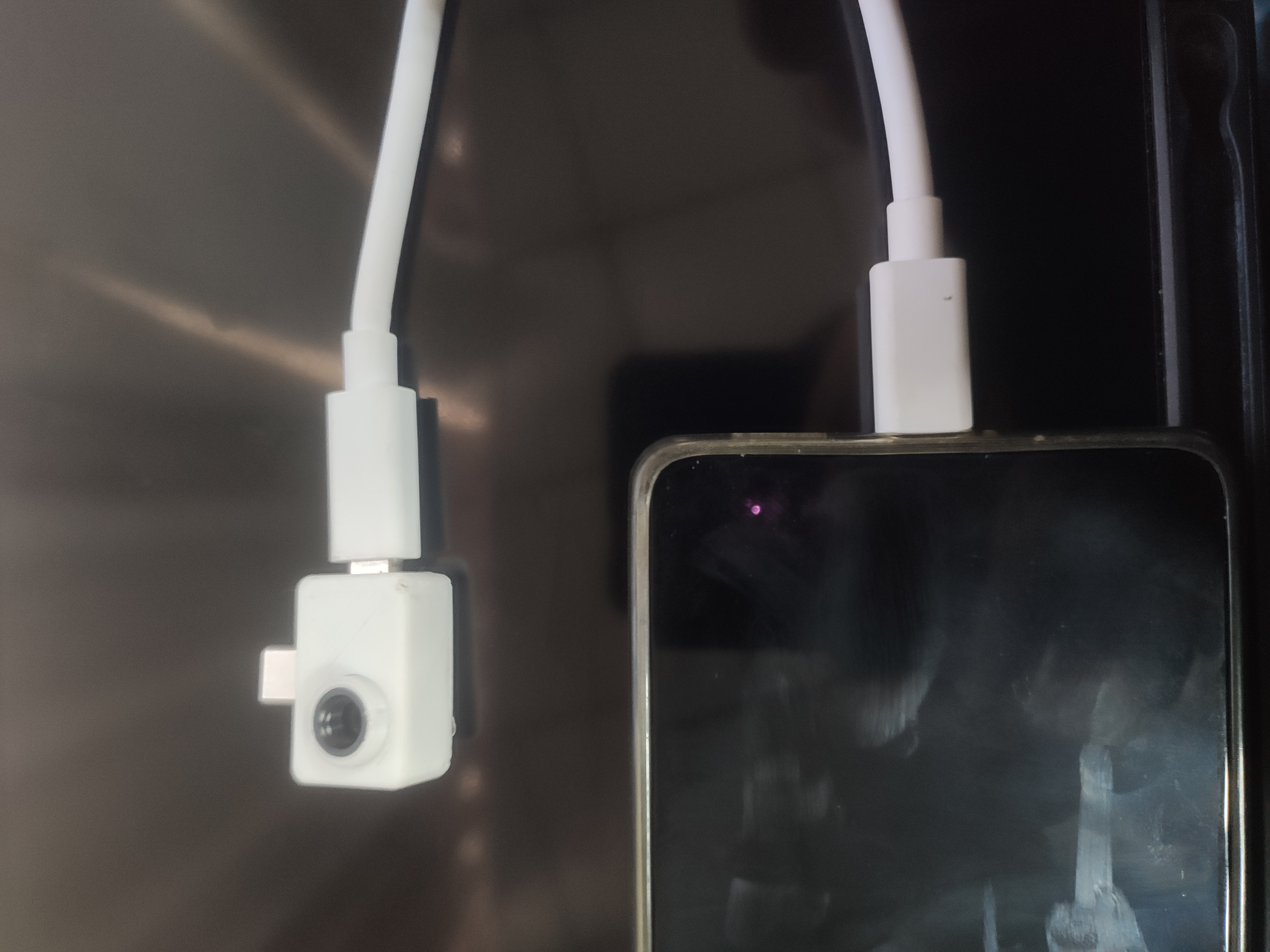
 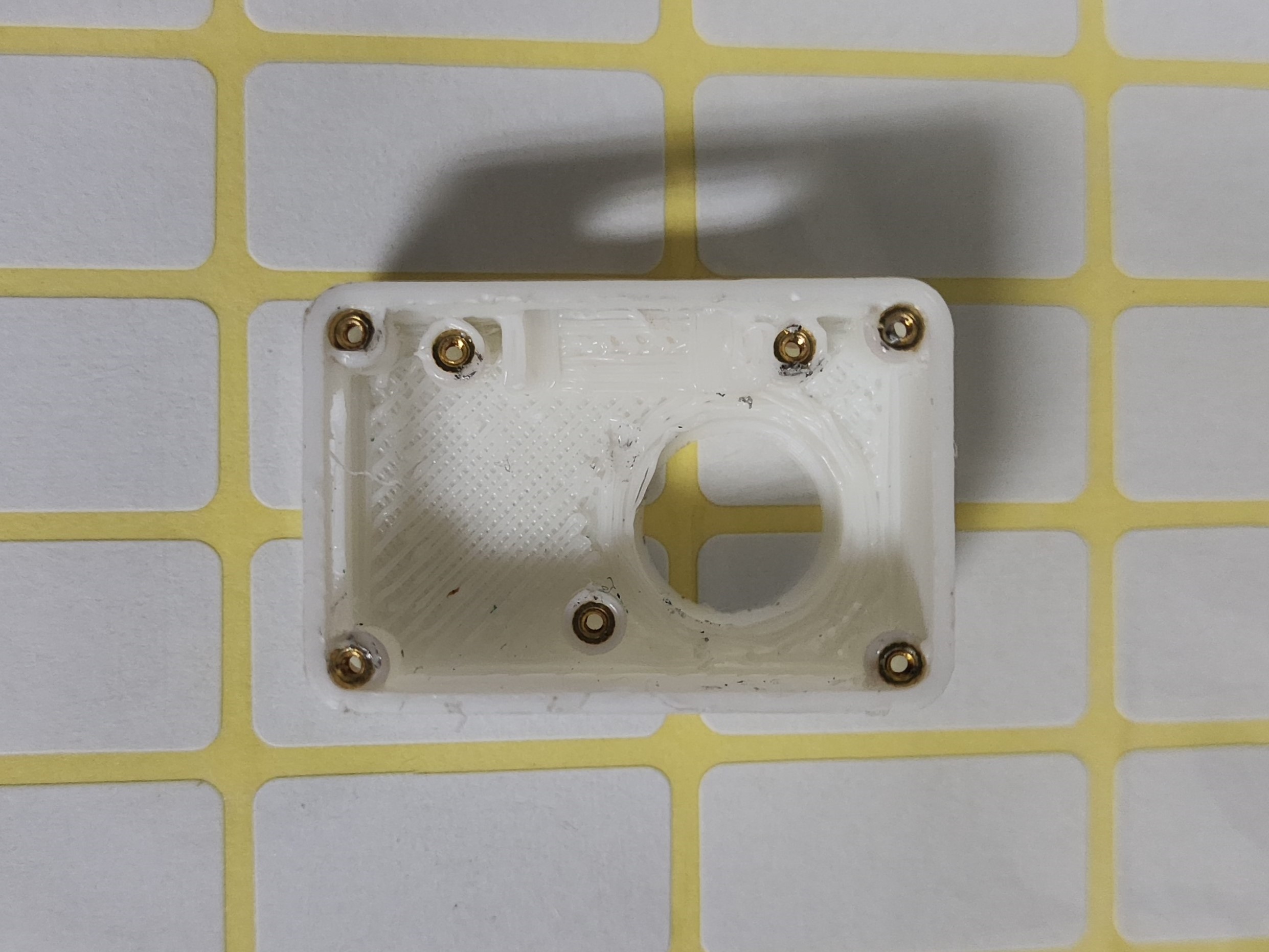 First, solder the pin headers to the Type-C board (the first PCB). This is crucial; adjust the pin header length so that they are just exposed on the second PCB (the one with the main controller and sensors) for easy installation of the back cover. See the pin header port in the second image. (If you don't understand, continue reading.)
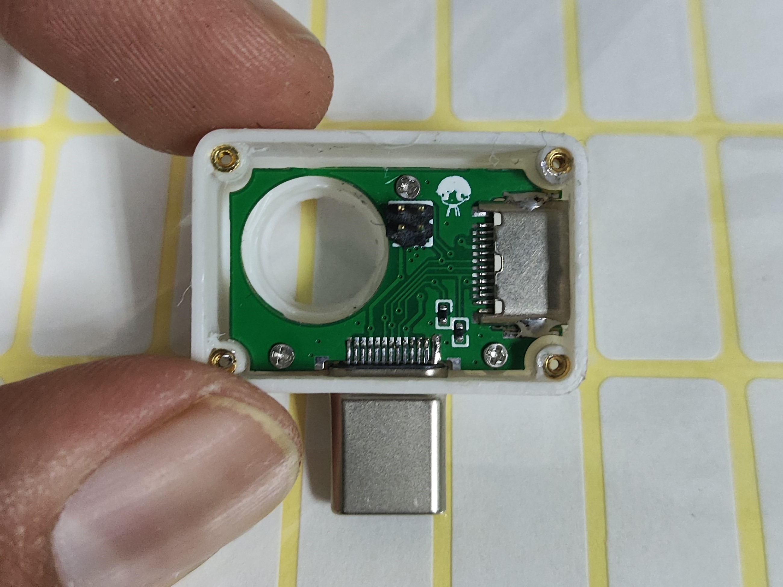
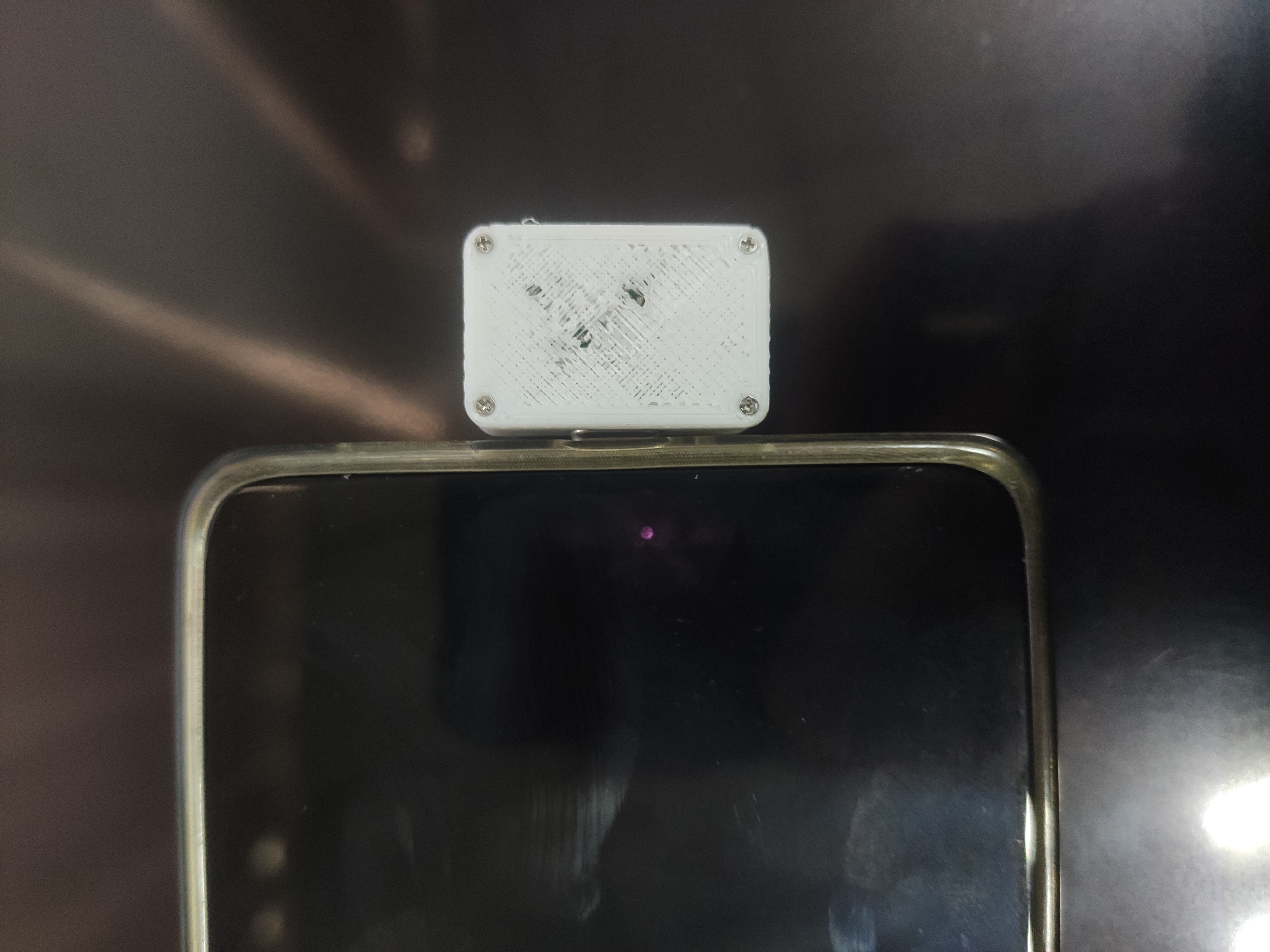
 The back cover has been slightly recessed where there is solder. You can apply a little B7000 glue to the edge of the back cover before screwing in the four screws.
 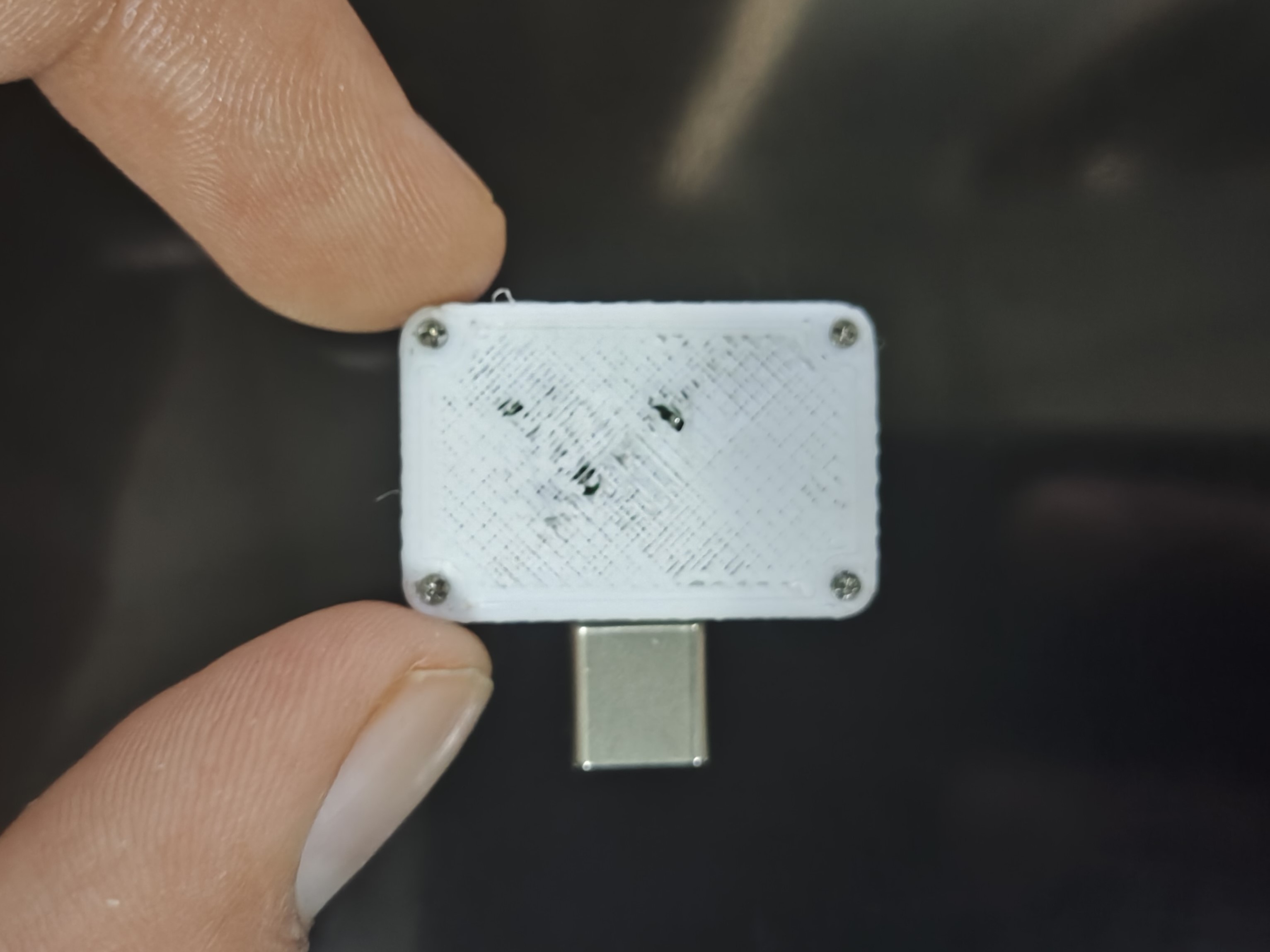 Manufacturing Instructions:
All reference designs on this site are sourced from major semiconductor manufacturers or collected online for learning and research. The copyright belongs to the semiconductor manufacturer or the original author. If you believe that the reference design of this site infringes upon your relevant rights and interests, please send us a rights notice. As a neutral platform service provider, we will take measures to delete the relevant content in accordance with relevant laws after receiving the relevant notice from the rights holder. Please send relevant notifications to email: bbs_service@eeworld.com.cn.
It is your responsibility to test the circuit yourself and determine its suitability for you. EEWorld will not be liable for direct, indirect, special, incidental, consequential or punitive damages arising from any cause or anything connected to any reference design used.
Supported by EEWorld Datasheet
EEWorld
subscription
account

EEWorld
service
account

Automotive
development
community

Robot
development
community

About Us Customer Service Contact Information Datasheet Sitemap LatestNews


Room 1530, 15th Floor, Building B,
No.18 Zhongguancun Street,
Haidian District,
Beijing, Postal Code: 100190
China
Telephone: 008610 8235 0740
 京公网安备 11010802033920号

 HFA200MD40D


