I. Driven by
interest, I spent some time studying the BLHeli_S code and some excellent open-source hardware to learn about open-source ESCs. However, its 32-bit version is no longer open-source, so I looked into AM32 firmware. The code link is: https://github.com/AlkaMotors/AM32-MultiRotor-ESC-firmware. This project is constantly being updated; I downloaded version 1.95. For testing, I initially wanted to build a PCB directly, but found that the main control chip used was either out of stock or several or even over ten yuan expensive. Since I was also learning RISC-V recently, I decided to switch to a different platform, which ultimately yielded good performance and cost-effectiveness.
II. Detailed
Explanation of the Selected Main Control Chip: The WCH CH32V203F8U6 features a maximum clock frequency of 144MHz, 64KB FLASH, 20KB SRAM, one advanced timer, three general-purpose timers, and a built-in SysTick core (emphasizing the timers here, as the AM32 firmware requires six timers internally, detailed later). It also includes an OPA, which can be used directly as a comparator for zero-crossing detection. Overall, it easily handles ESC applications, and its price is relatively low. Although I have a sample chip, even the large-package sample only costs a little over three yuan.
For better testing, a 5V/1A BEC output was implemented on the board using an LDO. If the power is insufficient, a suitable DC-DC converter can be used instead. The MOS pre-driver uses the commonly used FD6288Q. The two manufacturers' chips available in the market have different power supply voltage ranges and low-voltage protection thresholds. The schematic directly uses the battery voltage for power supply, which should not be a problem for common 2-4S batteries.
The program has been ported to MRS, allowing direct debugging using WCH-LINKE. The BootLoader has also been ported; initial flashing requires using WCH-LINKE to flash the BootLoader, after which AM32 configuration tools can be used to configure and upgrade the ESC's code. The AM32 firmware uses six timers: an advanced timer driving PWM, capable of outputting complementary three-phase PWM; a commutation time counter; an advance commutation counter; a 10kHz timer interrupt for PID control and periodic tasks; an input capture and output compare timer for throttle signal detection and communication; and a timer for delay. V203, as mentioned earlier, has five timers, so the delay is replaced by a NOP instruction in the program. TIM1 is used for PWM output, TIM2 for throttle signal detection, TIM3 for advance commutation counting, TIM4 for commutation time counting, and SysTick for the 10kHz timer interrupt.
Simultaneously, zero-crossing comparison is performed using the internal OPA. The outputs of the two OPAs are connected together (they can also be disconnected, and their respective IO interrupts can be used directly), and simultaneously connected to PA2, using PA2 as the final entry point for the zero-crossing comparison interrupt. The IO port allocation is as shown below:

Note: In the actual schematic diagram, only voltage and temperature detection are performed. PA6 is not used for current detection, but instead has an LED connected. If needed, you can directly modify the connection of the sampling resistor and current amplification and connect it to PA6, and directly modify the relevant ADC program.
III. Usage Steps
1. Burn the BootLoader to the bare board using WCH-LINKE. If you are unsure about the soldering, you can first supply 5V from the 5V output of BEC, and then use LINK to connect the DIO and CLK on the board (remember to share a common ground) to burn the BootLoader.
2. After burning, you can use the AM32 host computer software. I am using version 1.82 (Esc_Config_Tool_1_82_WIN). However, it's important to note that the host computer and the ESC use a single-wire serial port. If you have an Arduino Nano board, you can directly flash a single-wire serial program onto it using BLHeliSuite. I directly ported its program to the CH32V003 (why this one? Mainly because I had the board and chip, and it's inexpensive!). Connect the LINK serial port directly to PD5 and PD6, then connect PC1 to the ESC's input interface. Power on the ESC, open the host computer, and click the following in sequence:

On the first connection, it will display "No EEPROM," because it's still a blank chip with no configuration values. Simply click "Send Default Settings" below to flash the default values. After successful flashing, power on again. Connect again and click "M1." This will display the default parameters we just flashed.

This proves that we have successfully flashed the BootLoader and can configure and upgrade the ESC program through the host computer.
3. Returning to the tool's FLASH interface, click "Load Firmware," select our compiled firmware, and then the "FLASH Firmware" button will pop up. Click it to start the program update. Wait for the program update to complete:

Now, power on again, connect the ESC, and you will find that the firmware has been successfully updated. Now you can test it.

For the specific meaning of these configuration values, please refer to the wiki in the repository, which is very detailed:
https://github.com/AlkaMotors/AM32-MultiRotor-ESC-firmware/wiki/ESC-Settings-Explained
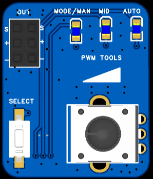
4. The following is the specific testing. The ported current version of AM32 supports PWM input, Dshot300, and Dshot600. So how do we generate these signals? There are some servo testers on Taobao, but they cannot output Dshot signals. So I went back to the CH32V003 and made another tester with it. By default, it is in PWM output mode upon power-on. The duty cycle can be adjusted by rotating the potentiometer. In PWM mode, a short press of the button can switch the PWM output between manual, intermediate value, and automatic scanning. Press and hold the button; the MODE/MAN light will flash slowly, indicating Dshot300 mode. Press and hold the button again; the MODE/MAN light will flash quickly, indicating Dshot600 mode. Long press to switch modes, short press to switch PWM output.
At this point, all preparations are complete, and you can connect the motor for testing.
IV. Attachments:
1. V003_OneWire.zip: Two-wire to single-wire serial port program;
2. Self-made servo tester data;
3. Host computer tools;
4. BootLoader program;
5. ESC PWM, Dshot300, and Dshot600 input no-load test;
6. Three signal waveforms for the test tool;
7. ESC main program reference: https://github.com/TianpeiLee/CH32V203_ESC.


 京公网安备 11010802033920号

 FX-104-DFF-D268


