
Project Introduction:
Thanks to the expert Molongdao for helping me adjust the rendering.
This project uses a Sigma Microelectronics SGL8022W (or Pinteng Technology PT8022W) touch dimming chip and a Prism Semiconductor LGS63032 boost LED driver to control eight Chengxing Optoelectronics XL-5730UWC-05 LEDs. An HT7533S is used to power the 8022W, with an external power supply voltage range of approximately 4.5~20V. The finished product can achieve touch control, with selectable stepless dimming, brightness memory function, or three-level dimming.
The shortcomings are that the final product requires an external power supply, and the power cord is rather thick, requiring further improvement. I couldn't find a suitable reference for battery power; I really don't know how to fit a battery in this size. Also, the touch area is relatively narrow, making it unsuitable for blind pressing.
Cost Statistics
Component
Quantity
Reference Price
PT8022W-S08
1
0.75744
10uF ±20% 63V
2
1.8648
XL-5730UWC-05
8
0.977608
LGS63032
1
0.983365
SS34
1
0.148136
HT7533S
1
0.236228
4.7uH ±20%
1
0.537
0Ω ±1% 125mW
4
A lump of solder
15kΩ ±1% 125mW
1
0.010741
47kΩ ±1% 125mW
1
0 (No soldering required when using PT8022W-S08)
8.2kΩ ±1% 125mW
1
0.010556
270kΩ ±1% 125mW
1
0.010692
4.3Ω ±1% 125mW
1
0.017108
47nF ±10% 50V
1
0.039269
100nF ±10% 50V
1
0.023299
4.7uF ±10% 25V
1
0.076447
10uF ±10% 25V
1
0.070966
PCB
1
0 (Free from JLCPCB)
M3 Screws
2
0.08 (I believe you can find two screws in your inventory)
Conductive Copper Foil
1
2
Total Price: 7.84
This LGS63032 has actually increased in price; it was only 70 cents a piece when I bought it before.
The reference price for ordering directly from LCSC Mall is 34.72. Excluding surface mount resistors and capacitors, the reference price is 15.00.
The original version previously sold for 198 in the flagship store, but it's sold out and removed from
the shelves. Regarding the replica
model
: I only tested the first version by printing. I modified the second version to address some issues, but it hasn't been printed or assembled yet.
The first version test revealed that the hardness of the UV-cured printing material was insufficient for the "head" model, making it prone to breakage during assembly.
The currently uploaded model has a wall thickness of 1.5mm. Testing showed it can be printed using FDM, with better results using transparent materials. Using colored materials might result in excessive thickness. I can upload model files with greater thickness if needed.
The model basically meets the design requirements for a 3D monkey model. The "leaf" model lacks cutouts and material escape holes; please create your own shells before uploading and printing.
The model size is limited by the maximum size of my college printer. If you want to make it larger or smaller, you need to adjust the stud size after scaling. As a
PCB
novice, this is my first time doing this kind of project. I tested two PCB prototypes, and both failed. In the final version, I only soldered the perforated board and redesigned the PCB. Theoretically, it should be fine.
The PCB size meets JLCPCB's free order requirements. For the order options, refer to: aluminum substrate AOI full testing + flying probe sampling (free), other options are default, personalization is optional.
Prioritize capacitors and resistors based on what you have; you can adjust some voltage divider/current limiting resistors and capacitor voltage ratings as needed.
The three chips are all small, making soldering difficult and costly; a heated soldering station is recommended, with careful control of heating time.
Soldering the aluminum substrate requires a high-power soldering iron; my 60W soldering iron can solder wires. I suggest using a heated soldering station for larger components. If you're worried about burning the chips, you can use a soldering iron, but solder bridging on the leads is difficult to handle. I don't recommend a hot air gun; during my testing, it was practically impossible to solder with one, and the LED would be ruined.
The power cable runs from the slot to the board, then through a hole at the bottom to connect to a DC female port for an external battery or adapter. It does look a bit ugly from the back.
The inside of the bangs model needs to be covered with conductive copper foil. A wire is soldered from the test point to the touch pin, passing through a via and soldered to the copper foil. My prototype used solder foil, which also worked.
The two control pins can be directly soldered with a lump of solder; you can refer to the 8022W datasheet for configuration, with OPT1=1 and OPT2=0 recommended.
Note that the aluminum substrate is not insulated around the edges, so avoid short circuits.
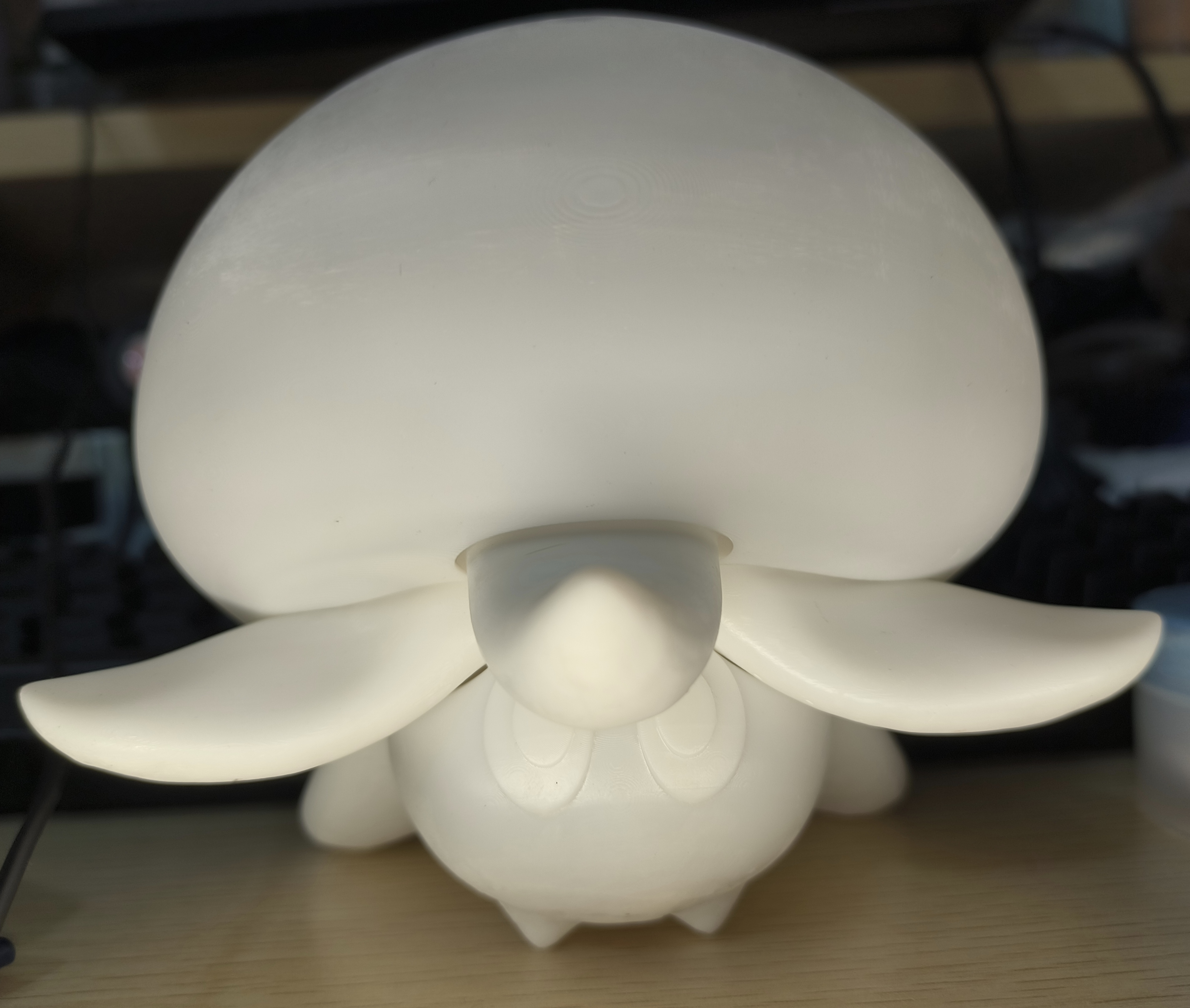
The finished product shown here
is the prototype version; I don't have the equipment for painting it. Personally, I feel that painting it is very easy, and you are welcome to try it.
Video link: https://www.bilibili.com/video/BV17N4y197mb/


 京公网安备 11010802033920号

 APL5507-18XC


