Project Description:
This is a 32-bit brushless quad-core ESC based on AM32/HF32 firmware, suitable for multi-rotor aircraft, climbing vehicles, boats, and other fields.
Open Source License:
This hardware design is released under the CC-BY-NC-SA 4.0 license for DIY learning and exchange purposes only. Commercial use in any form is strictly prohibited. This design is provided "as is" without any guarantee of employment or warranty. We are not responsible for any damage or loss to the creator or any third party's personal property or resources caused by improper product design, operation, or violation of local laws and regulations.
CC-BY-NC-SA 4.0, Creative Commons Attribution-NonCommercial-ShareAlike License.
CC: Creative Commons license.
BY: Attribution. You must give appropriate credit, provide a link to this license, and indicate whether modifications were made (to the original work).
SA: ShareAlike. If you remix, transform, or build upon this work, you must share your contributions under the same license as the original.
NC: Non-commercial use only. You may not use this work for commercial purposes without permission.
Project-Related Functionality
Product Overview
32-bit Processor: Based on a 32-bit processor, it provides higher processing performance and accuracy, facilitating higher levels of flight control.
Four-in-One Design: Integrates four independent ESCs, facilitating installation and commissioning in small multi-rotor aircraft. Reduces wiring connections and onboard space.
Supports Multiple Motor Protocols: Servo PWM, Dshot300, Dshot600.
Onboard Current Meter Design: Real-time current can be viewed via the flight control ground station. (Power Baseboard Onboard)
Wide Speed Range: Offers a wide speed range, allowing users to adjust according to different application needs.
Configuration Tool: Provides a visual configuration tool, Esc_Config_Tool, allowing users to easily adjust parameters and configure ESCs to adapt to different flight requirements.
Firmware Upgrade: Firmware upgrades are available via Esc_Config_Tool, allowing users to enjoy new features and performance improvements over time.
Lightweight Design: Employs a compact design, minimizing PCB size as much as possible without compromising performance to meet the weight and space requirements of aircraft.
Open-source firmware: The AM32 firmware is open-source, allowing users to modify and customize it as needed.
Wide applicability: Suitable for multi-rotor aircraft, climbing vehicles, boats, etc.
Product parameters
: Dimensions: 29.6mm*22.6mm*4mm (Half-hole core board for control section) 40.559mm*47.201mm*5mm (Baseboard for high-power MOSFET section) 40.559mm*47.201mm*7mm (ESC)
Operating voltage range: 10~40V, recommended power supply using 3~6s model aircraft batteries, maximum 8s.
Main controller: AT32F421K8U7: Arteritech ARM® Cortex®-M4 microcontroller, with a CPU processing speed of up to 120MHz and a built-in digital signal processor (DSP), supporting up to 64KB Flash memory and 16KB SRAM.
Gate Driver: FD6288Q: Integrates three independent half-bridge gate driver IC chips, designed for high-voltage, high-speed driving of MOSFETs and IGBTs, operating up to +250V.
Ammeter: INA199: Bidirectional, zero-drift, low-side or high-side, voltage output, current shunt monitor.
Buck: Employs SY8303 high-efficiency synchronous rectification, a step-down DC-DC converter capable of providing 3A of current, reducing the supply voltage to 8V to power the gate driver.
Ldo: Employs CJA1117B-3.3 low-dropout linear regulator to power the 32-bit main controller.
PCB Design: Uses a design separating the control section's half-hole core board and the high-power MOSFET section's baseboard. The core board uses a 4-layer design, and the baseboard uses a 6-layer design.
Firmware: AM32/HF32 .

Project Attributes:
This project is being publicly disclosed for the first time and is my original work. The project has not won any awards in other competitions.
Project progress:
2024/01/01 -- 2024/02/16 Completed the hardware design of this ESC using JLCPCB Professional Edition.
2024/02/17 -- 2024/03/25 Awaiting prototyping and learning open-source firmware AM32/HF32.
2024/03/26 -- 2024/03/27 Soldering the circuit.
2024/03/28 -- 2024/04/01 Testing the relevant functions of the ESC and conducting flight tests.
Design principle and
hardware structure block diagram
: Four-in-One Electronic Speed Controller (4-IN-1 ESC). Its hardware mainly consists of a core processing unit, power management unit, back EMF detection circuit, gate drive circuit, three-phase inverter bridge circuit, and current detection circuit.

The power management unit
(EMU) consists of a BUCK circuit and an LDO circuit. The BUCK circuit steps down the approximately 24V voltage from the power battery to 8V to power the gate drive circuit. The 8V output from the BUCK circuit is then stepped down to 3.3V by the LDO to power the ESC main controller and the ammeter. The power tree diagram is shown in the figure.

The low-dropout linear regulator section uses the CJA1117B-3.3, which has a fixed output voltage of 3.3V, a current output capability of 1A, and extremely low noise characteristics, making it suitable for powering the four main controllers of the ESC.
For the step-down DC-DC converter in the BUCK circuit, the design selects the SY8303AIC synchronous high-efficiency rectifier step-down DC-DC converter. Compared to traditional asynchronous rectification, synchronous rectification technology uses MOSFETs with extremely low on-state resistance to replace rectifier diodes, thereby greatly reducing the losses in the rectifier circuit and improving the efficiency of the DC/DC converter. Regarding its output voltage, this design controls the output voltage of the BUCK circuit by determining the ratio of the voltage divider resistors at the FB terminal of the SY8303AIC. According to the SY8303AIC datasheet, the relationship between the output voltage and the ratio of the voltage divider resistors at the FB terminal is as follows:

where R1 is the upper voltage divider resistor and R2 is the lower voltage divider resistor. Based on the above formula, when an 8V output voltage is required for the BUCK circuit, R1 is selected as 110KΩ and R2 as 9.1KΩ. The schematic diagram of the BUCK circuit is shown in the figure. The back EMF

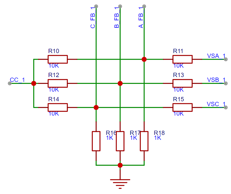
detection
circuit of the electronic speed controller mainly consists of a voltage divider circuit and a zero-crossing comparator circuit.
A brushless DC motor sequentially excites the windings on the stator through an electronic controller to generate a rotating magnetic field. The generated rotating magnetic field then interacts with the permanent magnets on the rotor, thereby generating electromagnetic torque and driving the rotor to rotate. The electronic controller must accurately know the real-time position of the rotor, because we can only perform commutation after we know that the rotor has reached the predetermined position, so that the motor can run smoothly. There are three common methods for rotor position detection:
(1) Based on voltage zero-crossing comparison, the rotor position is detected by comparing the three-phase voltage with the neutral point voltage of the motor. The advantage is that there are fewer connecting wires and the hardware circuit is simplified. The disadvantage is that open-loop control is required at startup, which may lead to poor control performance at low speeds, and the hardware circuit is relatively complex.
(2) Detecting the rotor position by installing Hall sensors, by installing three Hall sensors spaced 120 degrees apart on the motor, the position of the rotor is detected by the change of the magnetic field. The Hall sensors can provide accurate information about the position of the rotor magnetic poles, thereby achieving accurate commutation control. The advantage of this method is that the circuit structure is simple, but it increases the cost of the motor.
(3) Adding a magnetic encoder to directly detect the exact position information of the rotor. This method is costly and typically used in applications requiring high-precision position feedback.
After a detailed comparative analysis, this design decided to use a voltage-based zero-crossing comparison method to detect rotor position, as UAVs generally do not require low-speed operation, thus avoiding the problem of poor control performance of zero-crossing comparison at low speeds. Furthermore, the sensorless control strategy employed in the brushless motor drive system simplifies the system's hardware architecture, reduces the number of connections between the motor and the driver, and thus reduces overall system complexity. In addition, the reduced use of external components effectively controls system cost and stability. The purpose of the voltage divider circuit is to reduce the back EMF generated by the motor windings to a voltage range that the microcontroller can handle, thereby providing the necessary voltage reference for brushless motor control. The purpose of the zero-crossing comparison circuit is to capture a zero-crossing signal during brushless motor operation when the back EMF gradually rises from negative to above the motor's neutral point voltage, or when the back EMF gradually falls from positive to below the motor's neutral point voltage. This signal serves as feedback for rotor position. This feedback allows the motor's electronic control unit to accurately identify the optimal timing for current commutation, thereby achieving smooth motor operation and high-efficiency conversion, ensuring the continuity and stability of power output. The schematic diagram of the back EMF detection circuit is shown in the figure.
The gate driver chip selected for the gate drive circuit
is the FD6288Q, primarily because this chip integrates three independent half-bridge gate drivers. This high integration reduces the number of external components, thereby lowering the risk of failure. Furthermore, the FD6288Q supports high-voltage operation, possesses high-speed switching characteristics, and incorporates overcurrent protection and undervoltage lockout mechanisms, enhancing the overall stability of the system. The bootstrap diode and bootstrap capacitor are key components of the gate drive circuit. The functions of these two components and the key considerations when selecting them are explained below.
The bootstrap diode primarily provides a charging path in the gate drive circuit, allowing the bootstrap capacitor to be charged and maintain the required voltage level in each switching cycle. When the low-side switch is turned on, the bootstrap diode allows current to flow, charging the bootstrap capacitor. Simultaneously, the bootstrap diode helps prevent voltage overshoot and noise in the gate drive circuit, thus protecting its stability. When selecting a bootstrap diode, a diode with high reverse breakdown voltage and short reverse recovery time should be chosen. Because a high reverse breakdown voltage ensures that the bootstrap diode can withstand high voltage surges during high-side switching. A short reverse recovery time means the bootstrap diode can quickly switch from forward conduction to reverse cutoff. In brushless motor drive applications, a short recovery time allows for higher switching frequencies and reduces energy loss during switching transitions, thereby improving motor control accuracy and response speed. Based on these two characteristics, this design selects the 1N4148WTQ-7 switching diode as the bootstrap diode. Its 80V reverse breakdown voltage and 4.0ns reverse recovery time ensure high reliability and stability in high-frequency switching operation. The
bootstrap capacitor stores energy to provide voltage to the gate drive circuit when needed. In the half-bridge drive circuit, the bootstrap capacitor is charged through the bootstrap diode when the low-side switch is on, and discharges through the output of the gate driver when the high-side switch is on, providing voltage to the gate of the high-side MOSFET.
When selecting the bootstrap capacitor, a ceramic capacitor is chosen, and its capacitance is calculated according to the following formula.

Where Cbs is the capacitance of the bootstrap capacitor, Qg is the gate charge of the MOSFET, Vcc is the supply voltage of the FD6288Q, and Vf is the forward voltage drop of the bootstrap diode.
Based on the design of the ESC's power management unit, Vcc is 8V. According to the MOSFET and diode datasheets, Qg is 143nC and Vf is 1V. Substituting these three variables into the formula yields the minimum capacitance of the bootstrap capacitor: 204.29nF. Considering that a capacitance much larger than the calculated 204.29nF would increase the circuit's charging and discharging time, affecting the system's response speed and dynamic performance, and a capacitance smaller than 204.29nF would not provide sufficient charge to store adequate transient response, resulting in insufficient gate drive voltage, a 1μF ceramic capacitor with a 50V withstand voltage and a 0402 package was ultimately selected to ensure high reliability and stability during high-frequency switching operation. The gate drive circuit schematic is shown in the figure.

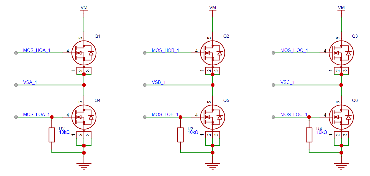
A three-phase inverter
bridge circuit consists of six MOSFETs, divided into upper and lower arms, each with three switching devices to control the switching of the three-phase current. The gate pull-down resistors of the MOSFETs play a crucial role. When the MOSFET's drive signal is removed, the pull-down resistors provide a discharge path, allowing the gate capacitance to discharge quickly. This process ensures that the MOSFETs can be turned off quickly and accurately, avoiding energy waste and potential thermal damage caused by untimely removal of the drive signal. Simultaneously, the presence of the pull-down resistors ensures that the MOSFETs remain in a stable off-state at a low potential when there is no drive signal, effectively preventing malfunctions caused by external interference or internal noise. When selecting MOSFETs, the drain-source voltage must be higher than the ESC input voltage and the voltage spike generated by the motor's back EMF, and the continuous drain current should be able to withstand the maximum current in the circuit. Furthermore, the MOSFET's on-resistance must also be considered; this is the equivalent resistance when the MOSFET is turned on, which generates heat when current flows. Selecting MOSFETs with low on-resistance helps reduce power loss and improve efficiency. Considering the above three points, this design selects the NTMFS5C410NL MOSFET. The relevant parameters of this MOSFET are as follows: Vds is 40V. The maximum continuous drain current is 230A at an ambient temperature of 100°C. At a gate-source voltage of 10V, the minimum and typical on-resistance are 0.65 mΩ and 0.82 mΩ, respectively. The schematic diagram of the three-phase inverter bridge circuit is shown in the figure.
The current
sensing circuit is used to accurately measure the total current flowing through the motor phase lines in the electronic speed controller. Dividing the battery capacity by this current gives the remaining battery life. Through the above calculation, the remaining usage time of the drone can be determined. The ammeter selected is the INA199A, a bidirectional, low-side, zero-drift, voltage-output current sensing amplifier. The schematic diagram of this circuit is shown in the figure.

Software Description
Firmware Description: (Currently using AM32 firmware version 1.99) The product firmware uses the open-source AM32-MultiRotor-ESC-firmware from GitHub.
AM32 Firmware Address: GitHub - AlkaMotors/AM32-MultiRotor-ESC-firmware: Firmware for STM32F051 based speed controllers for use with multirotors.
AM32 features include:
firmware upgrades via Betaflight pass-through, single-wire serial, or Arduino (PowerWriter recommended);
servo PWM; D-shot (300, 600) motor protocol support;
bidirectional D-shot
KISS standard ESC; telemetry;
variable PWM frequency
sinusoidal start mode designed to accelerate larger motors.
Firmware flashing steps:
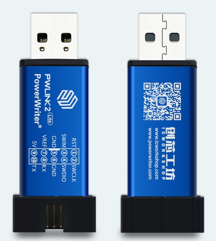
① After soldering the ESC control section half-hole core board, the bootloader needs to be flashed (this flashing step needs to be performed 4 times). The flashing tool and flashing documentation will be attached. You need to prepare your own PowerWriter programmer (as shown in the picture below).
② Connect the PowerWriter programmer to the flashing points on the ESC control section half-hole core board. Connect VREF (3.3V) to V, GND to G, SWCLK to C, and SWDIO to D.
③ Open Power Writer and connect
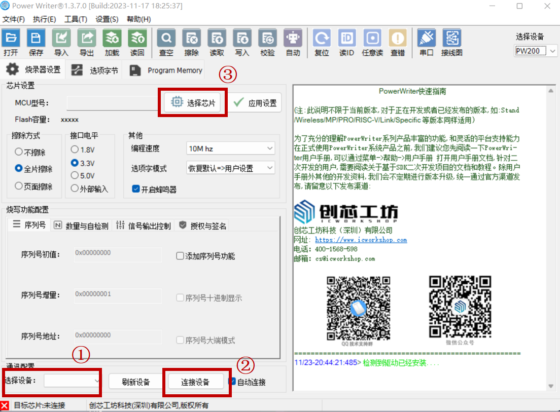
to the target chip. ④ Connect the target chip AT32F421x8 and click "Program Memory".

⑤ Load the required bootloader.hex file (AM32_F421_PB4_BOOTLOADER_V4.hex) and then click "Write". (See the attached "AM32 Firmware Data" for details on the hex file.)

Repeat the above steps four times to flash the bootloader for all four AT32 main controllers.
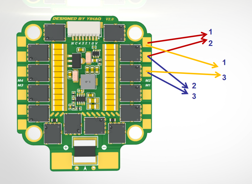
⑥ Connect the S1, S2, S3, and S4 ports of the control section's half-hole core board to the flight controller's motor interfaces respectively. Remember to pay attention to the order, i.e., connect S1~S4 to the flight controller's motors 1~4 in sequence. Change the flight controller's ESC protocol to DSHOT600.
⑦ Open Esc_Config_Tool to flash the AM32 firmware. Note that you need to manually select M1, M2, M3, and M4. You also need to repeat the AM32 firmware flashing process four times.
(See the attached "AM32 Firmware Data" for details on the firmware.)
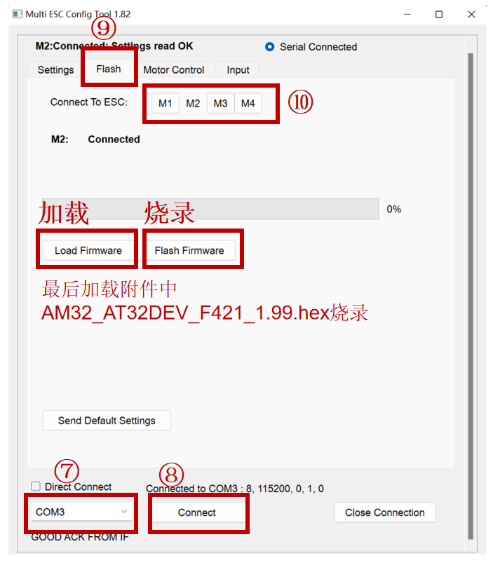
⑧ At this point, the AM32 firmware has been flashed for the ESC. Subsequent firmware updates only require repeating steps ⑥ and ⑦.
PS: HF32 firmware can also be flashed. See the video for flashing steps:
https://www.bilibili.com/video/BV1x4421S7CR/?spm_id_from=333.999.0.0&vd_source=193b179417eeab5eb2727825548d7fc1
The physical demonstration shows
the PCB of the four-in-one electronic speed controller, which uses a stacked design. Because the current flowing between the drain and source of the MOSFET is very large, by soldering the half-hole board of the control section to the base plate of the power section, a shorter path can be created for the high-current traces, thereby increasing the overcurrent capacity of the ESC.
The control half-hole board uses a four-layer design, with the stack-up relationship as follows: signal (top layer) – reference ground (inner layer 1) – power (inner layer 2) – signal (bottom layer).
The power base plate uses a six-layer design, with three layers being power layers and three layers being ground layers. Furthermore, the high-current trace section adopts the windowed soldering technique. This layout can achieve a wider trace in the high-current area, thereby further improving the overcurrent capability of the ESC. In addition, a large-capacity ceramic capacitor (MLCC) is configured on the bus to filter the power supply and absorb the voltage spikes generated by the back EMF of the motor. The MOSFET is placed close to the connected motor phase line to shorten the trace length, reduce resistance, and optimize the overall performance. The actual circuit board of the four-in-one ESC is shown in the figure below.

Fig
. (1) The front of the 4-IN-1 ESC and (2) The back of the 4-IN-1 ESC ESC
Demo Video:
No-Load Four-Channel Motor Drive Test Video: https://www.bilibili.com/video/BV1KQ4y157Rj/?spm_id_from=333.999.0.0&vd_source=193b179417eeab5eb2727825548d7fc1
On-Machine Test Video: https://www.bilibili.com/video/BV16K421y7kD/?spm_id_from=333.999.0.0&vd_source=193b179417eeab5eb2727825548d7fc1
Design Notes:
This design is provided as is, without any form of guarantee or after-sales warranty. We are not responsible for any consequences or related liabilities arising from product design, improper operation, or violation of local laws and regulations that result in damage to the person or property of the manufacturer or any third party.
The control board and power board are connected via the stamp holes around the perimeter; pay attention to the orientation.
Replicating this project is quite difficult. The smallest component uses a 0201 package, which is challenging to solder. It requires exceptional patience (potentially requiring multiple adjustments, and even crashes), as well as strong learning abilities and the capacity to solve problems through various methods, including but not limited to soldering, firmware flashing, and proper firmware usage. Therefore, this project is only recommended for model enthusiasts with experience in drone operation, proficiency in soldering surface-mount components, and a basic understanding of PCBs and components. Please carefully consider your hands-on and problem-solving abilities before deciding whether to replicate this project.
Power supply voltage selection: The theoretical maximum input voltage for this ESC is 40V. To allow for margin, a 3-6 second model aircraft battery is recommended, with an extreme limit of 8 seconds (not recommended).
Component selection: Filter capacitors need to be selected based on the input voltage (it is recommended to purchase capacitors from LCSC online store, as there are many cases of falsely advertised specifications on Taobao).
When soldering, please use silicone wire (28-30 AWG) to connect the flight controller to prevent the solder pads from detaching due to stress.
Pay attention to the wiring sequence! Pay attention to the wiring sequence! Pay attention to the wiring sequence!
A solid capacitor can be connected in parallel at the ESC power supply pads. Recommended values: 35V 1000uF or 35V 470uF. This is to reduce the interference of the ESC on the flight controller power supply.
The total component cost of the project is approximately 100 RMB, including the components on the power baseboard (the MOSFETs are refurbished and of fluctuating quality, for reference only). However, note that the cost of the ESC often only accounts for a small portion of the total cost of the drone.
After soldering, check before powering on and operating the motors. Always check for short circuits first. A simple method is to use the buzzer setting on a multimeter. Then, set the multimeter to the 200K ohm range and measure the resistance between any two pads at each motor connection point (three groups: 12, 13, and 23). Normally, the resistance should be between 21.3K and 21.9K ohms.
I
've recently heard some unfriendly comments, and the open-source environment for model aircraft is truly disheartening. It has also given me a breakthrough understanding of biodiversity.
① Some people are accusing me of deleting the database and running away. (Here, I'd like to clarify that this project is the first open-source 32-bit four-in-one ESC on the entire internet. Since I wrote such a detailed tutorial, I hope more model enthusiasts can benefit from it. And it's permanently preserved. If you can't see it, it's because I updated the documentation, and the LCSC platform is reviewing it, so it hasn't been released. I hope that when trolls criticize me, they'll understand the situation first and stop spreading rumors. PS: Even if I deleted the database, it wouldn't require your permission, would it?)
② My open-source flight controller and ESC. I invested a lot of time, energy, and money in its development. Having partners (currently only authorized by Mountain Eagle Technology FPV) approaching me for OEM cooperation is certainly a good thing; I get revenue, which motivates me to continue developing better products. Some people online are even saying that I designed my own ESC, and I can't even commercialize it? Since when is it forbidden to monetize knowledge? (Could it be that you can just sell my open-source products yourself? Yes, I'm talking about that "Mu Nian". Understand the open-source license before you start selling open-source ESCs and flight controllers to people other than me for profit. Now this ingrate is turning around and accusing me of something. The ESCs he sold had problems, and I kindly tested them without pay (because I was busy, it was delayed for half a year, during which time I did some basic testing and kept in touch with the buyer, who told me to do it when I had time). This Mu Nian even photoshopped the chat history, saying that I said "you can tell him not to worry about it". Why should he? Why should you, as the seller, not worry about the problems with the products you sell? It's obviously photoshopped and fabricated to absolve himself of responsibility and then pin it on me?)
③Those who say I plagiarized mainly say that I copied the open-source 8-bit four-in-one ESCs from the two masters sjj12345 and mtbsk8. This open-source ESC has two boards (one for control and one for power). The 32-bit and 8-bit power sections are similar, which is to be expected. The power board controls the MOSFETs and handles high current (anyone who has carefully read my documentation will know that the back EMF detection circuit, gate drive circuit, and three-phase inverter bridge circuit are all the same. Furthermore, the power supply sections are different; the only similarity is the MOSFET layout). The main difference between the 8-bit and 32-bit boards is the core control chip, peripheral circuits, and interfaces; the control sections are completely different. If we follow your logic, then all the MOSFET layouts from companies like ShanghaiTech, Aocoda, Xiugu, Beike, and Newtech are similar, meaning they're all plagiarism. Finally, I'd like to thank sjj12345 and mtbsk8 for their open-source contributions.
If you like it, please give it a like, comment, and share, or even a small donation (hehe, more support means more motivation!).


 京公网安备 11010802033920号

 1600BGH6008P2EB


