I. Project Description
This is a simple GPS cycling computer. I admired the cycling computers made by experts, but felt they were too difficult to implement. Seeing LCSC's ESP32 design competition, I took this opportunity to create this simple cycling computer. As its name suggests, it's a simple GPS cycling computer. Initially, I wanted to design all functions as modular systems, connecting all modules via adapter boards. However, in practice, I found that modular systems would result in a very large computer (and the current one is already quite large). Ultimately, I modularized the main controller, GPS, and display screen. The remaining components, such as the accelerometer, charging/discharging circuit, and SD card, were still designed on the main board.
II. Hardware Components
The hardware consists of four main parts: an ESP32C3 development board (without a serial port), a 4G+GPS module purchased online, a TFT module made using LCSC's open-source project, and an adapter PCB. The adapter PCB houses the charging/discharging circuit, MPU6500 circuit, SD card circuit, and a rotary encoder.
Since most components are modular, the circuitry on the main board is greatly simplified. The integrated charging/discharging circuit, MPU6500 circuit, SD card circuit, and a rotary encoder were all designed according to the manual or referenced from other open-source projects, with basically no changes. The reason for choosing the integrated charging/discharging circuit instead of the 4056 chips I already had is that the 4G+GPS module I bought requires a 5V power supply, and I didn't want to create a separate boost circuit, so I chose the IP5306 integrated charging/discharging chip.
I actually made two versions (actually three, the third version was improved but not printed). After making the first version, I found that the wiring of the TFT screen and the reserved wiring for the screen were reversed. After revising the second version, I found that the screen was intermittently malfunctioning. After two days of troubleshooting, I found that it was caused by placing the SCL under the boost inductor, which caused signal turbulence. This was temporarily solved by using a jumper wire. To explain this problem, on the one hand, I didn't pay attention when revising the second version; in the first version, I specifically avoided the inductor. On the other hand, I thought that since it's a closed inductor, it shouldn't have much impact, but in reality, it had a significant impact. The PCB routing in the final version has been adjusted.
Another issue is the MPU6500. I bought three chips from three different stores on Taobao, soldered them onto three boards, and after some tweaking, they still weren't generating data. Finally, just before the project deadline, one of them started generating data. I don't know if it was due to poor soldering skills or if the chips themselves were faulty.
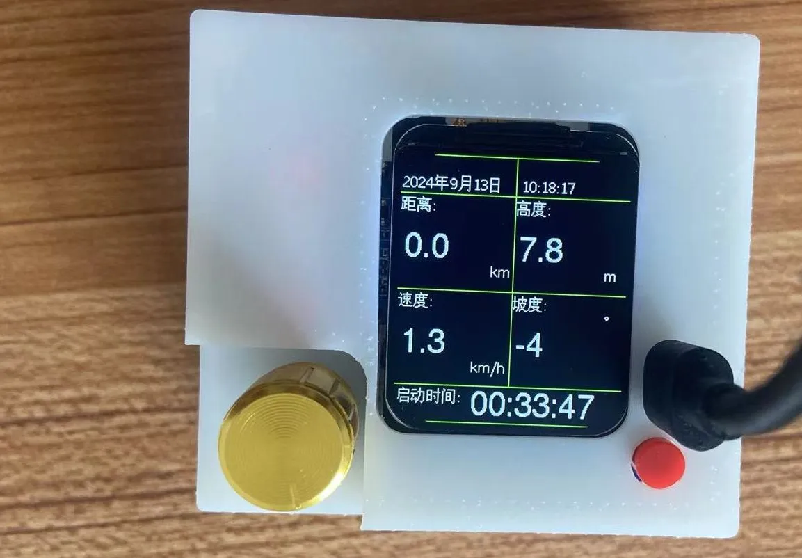
Thirdly, the software part
uses the tinyGPS and MPU6050 libraries from Arduino to implement the function of controlling the 4G+GPS module to receive GPS data and read angles from the MPU6500 via the main controller. This is a relatively basic and core function. I will continue to enrich and optimize the software later, adding SD card, button, and MQTT functionality.


 京公网安备 11010802033920号

 PAC27A01TR


