How to build a soldering iron heat controller circuit using microwave parts?
Source: InternetPublisher:拿铁三分糖 Keywords: Controller circuit soldering iron microwave oven Updated: 2025/03/11
In this post we will learn how to scavenge discarded microwave oven parts to make a useful soldering iron heat controller circuit which can then be used to maintain a controlled heat on the attached soldering iron tip, ensuring a safe soldering operation, which can be very important and handy if you are working with SMD parts.
Using discarded microwave parts
Do you have an old microwave that no longer works? Well, don't throw it away. If the display panel and touch buttons still work, you can make full use of it. Some cheap microwaves may not have adjustable power levels. If you can't adjust the power level to
50%, you won't be able to use this microwave.
Most defective microwaves are the result of a bad magnetron, a faulty high voltage diode, and/or a faulty high voltage capacitor.
Soldering iron tips do not last long when left plugged in for long periods of time. This project will allow you to set various power levels for your iron and automatically disconnect the iron after a time you set. View the functional block diagram of a typical microwave oven.
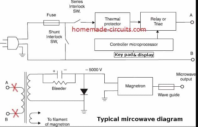
Working principle of microwave oven circuit
The lead marked with a red X indicates the AC connection to be disconnected. The processor controls the time that voltage is applied to the primary winding of the high voltage transformer based on the user's power setting.
If the 100% power setting is selected, the relay or triac supplies voltage to the transformer for 100% of the selected cooking time.
If the 50% power setting is selected, the processor will provide the transformer with 50% on time and 50% off time. Some microwaves can provide power levels as low as 10% and 90%
off time.
The transformer provides the high voltage to power the magnetron, which provides the heat for the oven. For this project, we are only interested in the power cord, fuses, keyboard, display, and processor, and the power cord to the transformer. There is no risk of radiation exposure from the magnetron when the microwave is unplugged from the AC power source.
The outer metal cover should be removed from the microwave, taking care not to touch any parts inside until the high voltage capacitors have discharged.
Before discarding the lid, note the wattage rating of your microwave. Using a metal screwdriver with an insulated handle, locate the high-voltage capacitor and place a short across the capacitor's two terminals. If the capacitor is still storing a charge, a momentary spark may occur.
Extracting parts from microwave to make soldering iron controller
The processor board usually has a ribbon cable connected to the keypad and LCD panel. The wires from the processor to the high voltage transformer primary will be heavy gauge wire that must be cut.
Clamp the wires as close to the transformer primary as possible. The primary is the small coil winding and the secondary is the large coil. The AC power wires must have continuity from the AC fuse to the processor panel. This will require removing interlock switches, thermal switches, and any other switches that would prevent AC continuity.
Depending on the make and model, the fuse may be located on the processor board or elsewhere in the case. You may need to remove the large plastic panel that contains the keypad and display panel. This panel can be shrunk down to fit the case you are building.
A hacksaw or dremel tool would be the best way to reduce the size of the panel. The enclosure for this project should contain the keypad and display panel mounted externally, and the processor board and AC fuse mounted internally. It should also contain an auxiliary AC outlet for a soldering iron or other device you wish to control.
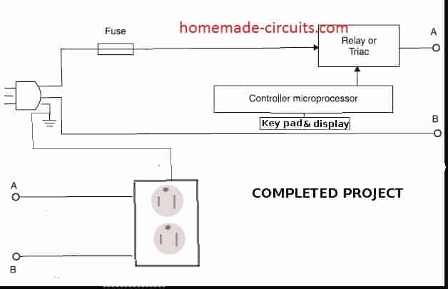
The two leads removed from the primary side of the high voltage transformer should be connected to the auxiliary socket on the case. The hot side of the AC, from the processor board, (usually black) should be connected to the side lugs, which connect to the small vertical blades on the socket. If longer lengths are needed, twist-type connectors can be used to splice the wires.
Use the same gauge wire as the original wiring. The neutral wire (white) should be connected to the opposite side lug of the larger vertical blade on the outlet. The green wire from the AC power cord should be spliced and connected to the green lug on the outlet that is connected to the small round female hole. A complete project diagram will be displayed for your reference.
Testing and Troubleshooting
Once that is done, plug in the power cord and test the panel. If it does not work, verify that you have AC power connected to the processor board. You may have left a switch of some type on the motherboard that must be removed.
Depending on what the switch or heat sink is for, you may want to disconnect it and leave the wires open, or tape them together on the processor board.
Make sure you understand the purpose of the device that blocks AC from entering the processor. Make sure you include an AC fuse in the circuit and that it is not blown.
The auxiliary socket for your iron should be marked with the maximum wattage allowed that you mentioned earlier. Once the keyboard is working properly, plug the desk lamp into the auxiliary socket and set the power rating to 100% and the time to 20 seconds.
Press the "Start" button on the keypad and the lights should come on for the selected period and then automatically turn off. Change the power level on the keyboard to
50%. The lights should remain at the same brightness but flash on and off with a few seconds between each cycle.
To use the soldering iron immediately, plug it in and set to 100% power. Set the time you want for your project and press Start.
If you need a short break, lower the power level to 50%. When you return, reset the power level to 100%
for faster heating. You may decide that your iron may require a higher or lower idle time power level to maintain a warm temperature.
More Applications Using Microwave Oven Parts
In the above discussion, we learned how to use parts from a discarded or broken microwave oven to make a heat controller circuit for a soldering iron, but you can find many other applications for using discarded microwave oven parts as well.
A small heating pad can be connected that turns off at a time of your choosing. If your microwave is set to 10% power, you can connect a table lamp that turns off and on for a few hours.
This may lead a potential burglar to believe someone is home. You can plug in a small reading light next to your bed and program it to stay on for as long as you need it to and then turn off automatically. Remember to follow the manufacturer's maximum power rating when connecting appliances or other electrical objects. Do not connect AC motors, electric drills, or other inductive loads to this outlet.
- The meaning and importance of circuit protection, common types of circuit protection
- Replace the GE LOGIQ a200 ultrasound measurement key with a self-made touch switch
- Working principle of ZNB-S digital display intelligent motor protector control circuit
- Motor control circuit for starting and running without phase loss
- Design and analysis of touch delay switch circuit composed of CD4011 and CD4001
- Design and analysis of a four-bit remote control component capable of remote reset
- Amplitude and phase detection leakage protection device designed and manufactured using PIC16C711A
- Delay switch made with LM431
- Infrared detection alarm
- Homemade anti-theft watchdog
- Timing and fire power control circuit
- Control circuit of Gao Shida 25860T microwave oven turntable assembly
- Time controller circuit for timing power on
- A transistor photoelectric controller circuit
- Electric mixer intermittent operation controller circuit
- Broadband shared power controller circuit
- High-end step dimming light controller circuit (2)
- Wanhe WK237 mechanical microwave oven circuit diagram
- Galanz WP700, WP750, WP800 mechanical microwave oven circuit diagram
- LG Electronics MC-5586DTW computerized grill type microwave oven circuit diagram


 京公网安备 11010802033920号