What are the advantages of solid-state relays? Solid-state relay insulation monitoring design scheme
Source: InternetPublisher:Lemontree Keywords: Relays Solid State Relays Insulation Monitoring Updated: 2025/03/07
In electric vehicles, solar panels, and energy storage systems, high-voltage power supplies enable faster charging times, minimize power losses, and increase design reliability. However, high-voltage currents have the potential to be dangerous or even deadly, so designers use insulation monitoring systems to send alarms or disconnect power to prevent harm to the application or user. Quickly and accurately detecting insulation faults is critical to maximizing user safety and minimizing damage or fire from catastrophic power outages.
Common applications for insulation monitoring include battery management systems, energy storage systems, string inverters, DC fast chargers, DC wall chargers, solar panels, motors, and aircraft. However, accuracy and withstand voltage testing requirements can make the design of insulation monitoring challenging.
Meeting the Design Challenges of Insulation Monitoring
Insulation monitoring, also known as insulation checking, isolation monitoring, isolation checking, ground fault detection, or ground fault detection, monitors the amount of insulation between the high voltage terminals and the protective earth/chassis ground. Figure 1 shows one configuration for insulation monitoring. The basic operation of the insulation monitoring circuit involves switching known resistors (RDIV1/2, RDIV3/4) and solving a system of equations to solve for the unknown insulation resistance (R/1A).
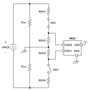
Figure 1: Insulation monitoring configuration
Meeting stringent safety requirements
Safety standards require manufacturers to assess the safety of a given electrical or electronic device's insulation by performing a dielectric voltage withstand test, also known as a high potential test. The dielectric withstand test applies a high voltage across the insulation barrier for one minute. Post-test measurements of insulation that meet the manufacturer's required threshold are considered a passing grade.

Figure 2 illustrates this withstand voltage test, using the previous insulation monitoring configuration, with the high voltage battery removed and 4,242 V applied across the terminals and chassis ground.

Figure 2: Example of insulation monitoring high potential
Since the switches (SW1, SW2) are typically solid-state relays or photo relays with integrated MOSFETs, component considerations must be made to ensure the survivability of the switch. These switches are typically rated for a limited avalanche current (Iava) over a period of time, so when selecting components, for example, you may need to select a series resistor that will sufficiently limit the avalanche current, or ground an expensive reed relay to prevent avalanche current from flowing altogether. Unfortunately, having a large series resistance can negatively impact measurement accuracy, so selecting a resistor with a value similar to the insulation resistance will maximize accuracy.
Advantages of Solid State Relays
You can use photorelays, but there are disadvantages in avalanche current, speed, reliability, and solution size compared to solid-state relays. The TPSI2140-Q1 supports up to 2 mA avalanche current, compared to 0.6 mA for general-purpose photorelays. The switching speed of general-purpose photorelays is also typically limited by their LEDs and forward bias requirements. Photorelays suffer from light degradation over time and size, requiring additional components to create a drive circuit.
Figure 3 shows the TPSI2140-Q1 functional block diagram.
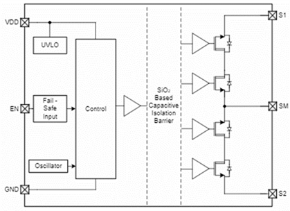
Figure 3: TPSI2140-Q1 functional block diagram
Depending on other system requirements, you may want to consider a configuration that uses an intelligent battery junction box, such as the BQ79731-Q1 battery pack monitor, to measure voltage, temperature, and current.
The AFE Reference Design for Electric Vehicle High-Voltage Charging and Solar Insulation Monitoring and the Automotive High-Voltage and Isolation Leakage Measurement Reference Design both use the TPSI2140-Q1 solid-state relay to switch known resistances.
Designers sometimes choose to purchase insulation monitoring modules to avoid the challenges of considering hipot test design factors. Both reference designs use different topologies to solve the insulation monitoring problem with good fault detection accuracy, support for safety standards, scalability, etc.
The AFE reference design accurately and reliably monitors insulation resistance, maintains insulation during insulation resistance measurements, and supports IEC 61557-8 and IEC 61851-23.
Figure 4 shows the AFE reference design block diagram.
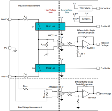
Figure 4: AFE reference design block diagram
Figure 5 shows the block diagram of the leakage measurement reference design.
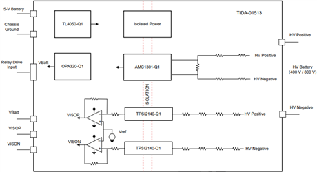
Figure 5: Leakage measurement reference design block diagram
in conclusion
The move to higher voltages to minimize charging times - such as the trend from 400 V to 800 V for electric vehicles and the move to higher voltage systems for solar - has increased the need for reliable safety and insulation monitoring methods. Insulation monitoring detects insulation resistance by monitoring the leakage current from the high voltage terminals to the protective earth/chassis ground. Since currents above 10mA can be lethal, insulation monitoring systems must warn when insulation faults are detected.
- Tutorial on making your own remote-controlled robotic arm
- Use your smartphone to turn on/off the power in your home
- A small improvement to the temperature and water level indicator alarm
- JDB-LQ-TQ/2 motor full voltage starting circuit
- Star-delta step-down starting control circuit for squirrel cage asynchronous motor
- Motor control circuit for starting and running without phase loss
- Methods for Eliminating Noise of Brushed DC Motors
- Design and analysis of touch delay switch circuit composed of CD4011 and CD4001
- A novel and practical power line anti-theft and cutting alarm circuit
- Night dog barking anti-theft reminder circuit
- Homemade disinfectant circuit
- Switching regulated power supply circuit
- sound control circuit
- Schematic diagram of motor PLC control circuit
- Typical operation display circuit
- Photoelectric detection output control circuit
- Microwave heating component control circuit schematic diagram
- Solid state relay circuit one a
- Dimming light circuit using parametric solid state relay
- Solid state relay automatic voltage regulator circuit


 京公网安备 11010802033920号