How to use LM317 as a switch to turn power load on and off
Source: InternetPublisher:zht24 Keywords: controller lm317 power switch power load Updated: 2025/03/04
Today we will learn how to use the LM317 as a switch to turn a power load on and off. It still has the same protection performance. Even though the frequency is higher. It all started when Dave asked in the 22Hz clock pulse generator circuit "Will this work for a 22vdc battery pack to provide 60VAC at 60Hz?"
The MM5369 CMOS we have used before is often used as a precision time base when using a quartz crystal and an RC network.
Typically, the MM5369 requires a wide range of voltages (3V–15V). Therefore, it should never be used with 22V voltage levels. It outputs very low currents because it is a small IC focused on power saving.
The concept of the circuit
Now let's take a look at a block diagram of what we want to achieve. It will help us visualize the circuit ideas we need.
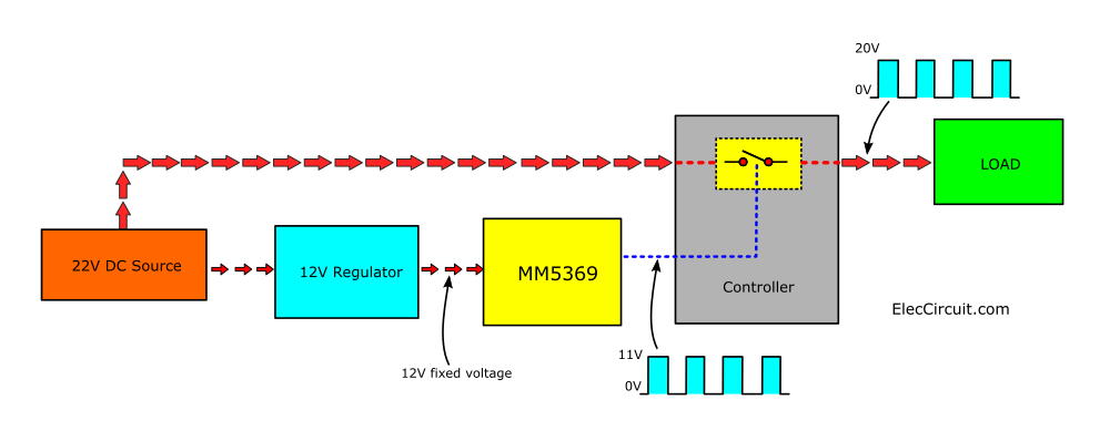
Block diagram to boost the voltage at the MM5369 output.
Each block can be divided into:
The 22V DC power supply is the only power source in this circuit.
The 12V regulator will provide a constant 22V voltage when powered by 12V. Because the MM5369 requires a stable voltage supply (12V fixed voltage).
The MM5369 module is a 60 HZ pulse generator or time base.
The controller acts like a general switch. It will connect the high power of the DC power supply to the output by controlling the signal of MM5369.
Load is a device used to test the circuit. It is connected to the output and requires high current.
The important point is that the output signal must have the same waveform as the signal from the MM5369. But it will also have a higher voltage level, from about 11V to 20V.
Select Components
Next step: Let’s select components based on the specified requirements, such as performance, size, and price.
12V Regulator Module:
We use a Zener diode regulator to provide a stable 12 V. Since IC1 requires less current, a simple circuit like this is sufficient.
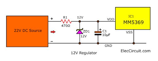
12V Zener Dode voltage regulator circuit, using 22V input voltage
We can easily calculate the value of R1 by:
R1 = (Vin-Vic1)/IIC1 = (22V-12V)/0.02 = 500
Input voltage = 22V, VIC1 = 12V, IIC1 = 0.02A
The wattage rating of R1 does not need to be more than 0.5 watts, since the power (P=VxI) is only carrying 0.02A x 10V = 0.2 watts.
So, we use R1 is 470 ohms 0.5W
Furthermore, we add C1 to increase the efficiency of this circuit.
Controller Block:
The simplest and most popular method is the transistor. This is a great switch. We can use the low voltage level at the base to control a high voltage load at the CE, just like a relay. But it works much better at high frequencies.
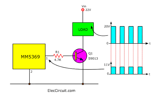
Small transistors used as simple switches
We tested it with an S9013 NPN transistor. But it can only be used with a load that consumes no more than 0.2 A. The shape of the signal at the output of IC1 and at the load remains the same, but the amplitude is different.
But when we want to use a load, which consumes more power, it is necessary to change the transistor to a transistor that can handle more current, such as BD139 or TIP41.
Using LM317 as a switch
But since we have a lot of LM317 regulators nowadays. They are very efficient and pretty cheap compared to traditional TO-220 transistors.
So it’s great that we learn to use it more.
Looking at the datasheet, the LM317 can accept a maximum voltage of 40V and a maximum output voltage of 37V, with a high output current of 1.5A.
But the interesting thing is that it has a good protection system when short circuit or over current occurs.
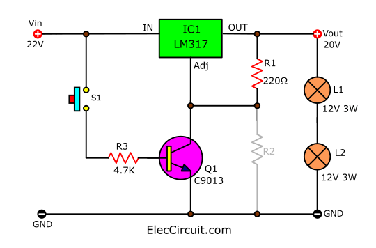
Let's do an experiment. In the circuit below, disconnect R2 and insert the S1 push button switch.
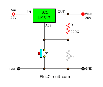 Experiment with LM317 as a switch
When S1 is not pressed, the output voltage is about 20V. But when we press S1, the voltage drops to about 1.2V.
Then, we change the position of S1 of Q1 to act as a switch. Then move S1 and try to press S1 again. To see the effect more clearly, we add a 24V3W lamp as a load. (We use 12V 3W bulbs in series.
When we release S1, both bulbs will light up, but when S1 is pressed, both bulbs will turn off normally.
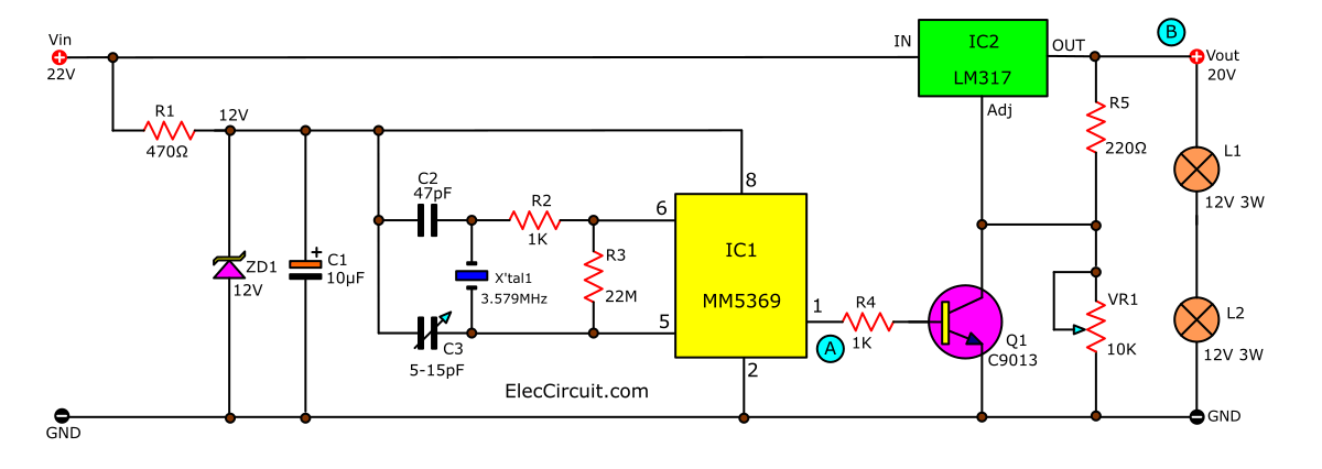
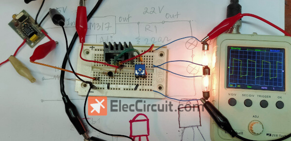
Next, let's try to put all the parts together to make it into a complete circuit.
We will see the light bulb turn on. The signal measured by the oscilloscope is very complete.
The signals at point A (output of IC1) and point B (output) have a phase difference of 180 degrees or are out of phase.
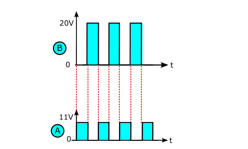
The output of the LM317 is 5369 degrees out of phase with the input signal of the MM180.
When the load is changed to one that consumes more power, the LM317 still works fine. It can provide a maximum current of 1.5A. We can also adjust the amplitude of the output signal with VR1, such as to 15V or 18V, etc.
in conclusion
By solving this problem, we used LM317. It works well. Although it is not perfect, it can help us learn to use LM317 more.
We are very happy with the LM317 as a switch because it is very flexible.
But it has some limitations:
The lowest voltage level is not 0V (but 1.2V).
When the frequency level is higher than 1kHz, the signal may be distorted.
There is always a level of loss within the LM317. As shown in the experiment, if the input voltage system is 22V, the output voltage will only be around 20V.
If we want to reduce this voltage loss, we should use transistors instead. But since we don't have such transistors yet, we can't experiment with them now.
- 12v high power battery charging circuit diagram
- What effect does the copper coating on the bottom of the inductor have on the power supply?
- Sharing layout and tips for multi-rail power supply design
- How much current can a 2N3055 solar cell produce? How can I get 3055V from a 12N2 solar cell?
- Schematic diagram of car cigarette lighter to USB power port
- How to use a simple circuit to achieve a smooth soft-start for an isolated converter
- Driving circuit of switching power supply field effect tube
- Transformerless AC-DC constant current LED driver circuit
- LED rechargeable flashlight circuit diagram
- Dynamic power supply for power amplifier controlled by thyristor
- An LCD and controller interface circuit diagram
- Electroplating driving PLC control ladder diagram
- Delayed turn-on regulated power supply circuit composed of LM317
- Control and protection circuit composed of master switch and cam controller
- Bird call simulator circuit
- Using NE555 to make an incandescent lamp life extension controller
- CJM03 composed of fuse scrap emergency controller
- Basic application circuit diagram of LM317
- stair lighting controller
- temperature range controller


 京公网安备 11010802033920号