What effect does the copper coating on the bottom of the inductor have on the power supply?
Source: InternetPublisher:张七岁 Keywords: Power supply inductor copper plating Updated: 2025/02/25
The inductor has an alternating current, and the copper at the bottom of the inductor will generate eddy currents on the ground plane. The eddy current effect will affect the inductance of the power inductor. The eddy current will also increase the loss of the system. At the same time, the noise generated by the alternating current will increase the noise of the ground plane and affect the stability of other signals.
From the EMC perspective, laying copper at the bottom of the inductor and laying copper on the complete ground plane is beneficial to EMI design. The current inductor production process has been upgraded, and the inductor uses shielded inductors. There are very few leaked magnetic flux lines, which has little effect on the inductor's inductance and is also beneficial to heat dissipation.
How to choose in actual engineering?
How to choose in engineering, we must first understand the structure of the inductor. The inductors we commonly use are non-shielded I-shaped inductors, semi-shielded inductors, and one-piece molded inductors. What are their characteristics?
The magnetic circuit of the unshielded I-shaped inductor is composed of a magnetic core and air. Its magnetic flux lines are completely exposed to the air without any magnetic shielding.
Semi-shielded inductors, as can be seen from their skeleton structure, are based on I-shaped inductors, with magnetic shielding materials added to the periphery of the inductor. Because the magnetic resistance of the magnetic shielding material is small, the magnetic flux lines are basically locked in the magnetic conductive material, and only a small part of the magnetic field will leak out from the air gap, so it can play a certain shielding role.
One-piece molded inductor, the winding and magnetic conductive material are cast at one time during the inductor production. There is only a small air gap inside to prevent the inductor from saturation, so this type of inductor basically has no magnetic flux overflow.
Experiment on the influence of copper skin of unshielded I-shaped inductor and shielded inductor on inductance.
Experiments have found that when the unshielded I-shaped inductor has copper skin, the inductance is reduced, while the shielded inductor has almost no effect.
What effect does the copper coating on the bottom of the inductor have on the power supply?
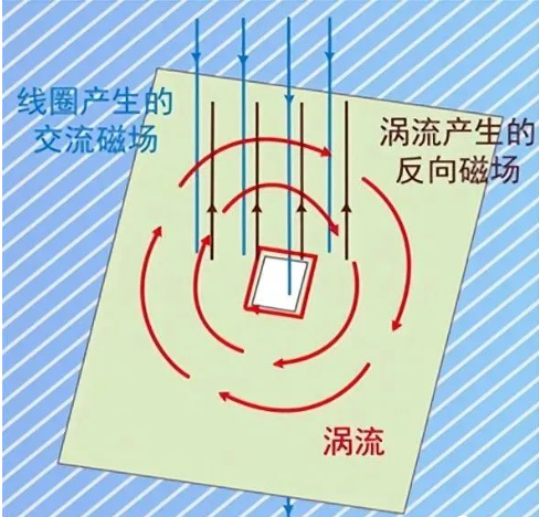
Before thinking about this question, let’s first review the eddy current effect. When the magnetic flux lines are from N to S level and there is an alternating magnetic field passing through the surface of a conductor, the law of electromagnetic induction shows that an induced current is formed on the surface of the conductor, and the direction of the magnetic field generated by the induced current will always weaken the original magnetic field.
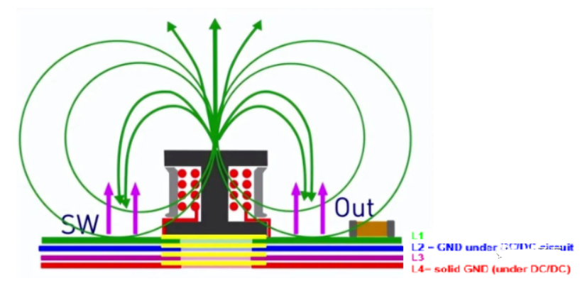
Below is the current loop of the Boost DC/DC circuit. Let’s talk about the impact of the copper plating at the bottom of the inductor on the power supply design.
When the boost voltage is working normally, the load current flows through the inductor to form a loop. Due to the presence of the switch tube, the current changes dynamically, which can form the magnetic flux lines of the inductor. On the surface of the conductor, part of the magnetic flux lines will form a closed magnetic loop, and part of the magnetic circuit will form leakage magnetic flux overflowing into the air. If there is no copper coating at the bottom of the inductor, the magnetic flux lines overflowing from the inductor will exist in the entire power supply system, leaving the system with no relatively quiet space, which will cause the EMI performance to deteriorate.

If the bottom of the inductor is covered with a complete copper, an eddy current effect will be generated on the bottom plane of the inductor, and the eddy current will offset the magnetic field generated by part of the leakage inductance, weakening the original leakage magnetic induction line. The eddy current generated by the copper coating on the bottom of the inductor acts like an electromagnetic shield, blocking the magnetic induction line from propagating downward, thus shielding the high-frequency magnetic field generated by the inductor on one side of the conductor, thus greatly reducing the impact of the high-frequency magnetic field on other components in the space.
From two perspectives, from the perspective of EMI, copper plating is recommended; from the perspective of inductance, it has no effect on the inductance of shielded inductors, so copper plating is also recommended, and only the bottom plating of the I-shaped inductor has a slight effect on the inductance, so in actual engineering it depends on the situation.
In the actual PCB layout, the filter output from the switch is placed on the PCB plane opposite to the inductor, which is more conducive to avoiding high-frequency interference in the filter components and preventing high-frequency interference from being transmitted through the line.
- TL431 functional pin diagram, DC linear regulated power supply solution based on TL431
- How to improve the accuracy and precision of power supplies through low frequency thermal noise?
- How much current can a 2N3055 solar cell produce? How can I get 3055V from a 12N2 solar cell?
- How to Make a Soft Latch Circuit
- Fabrication of multi-cell lithium battery charging circuit
- What kind of circuit is a voltage regulator circuit?
- Basic connection circuit of signal and power supply composed of ISOll3
- Parallel DC regulated power supply circuit diagram
- How to use SBR to improve power conversion efficiency
- Production of backup power supply for cordless phone
- Minimize noise and ripple using low-noise buck converters
- Machines are rare, hackers can actually steal data through the power supply
- For Schottky rectification, what are the advantages of synchronous rectification?
- Do you know about 180W and 220W high-efficiency adapter power supplies?
- How to avoid electrical stress in chip design, do you know?
- Do you know the possible reasons why the power adapter cannot be used universally?
- Circuit design considerations
- LCD TV power supply application circuit diagram
- Power circuit b composed of intelligent thyristor modules
- Power circuit a composed of intelligent thyristor modules


 京公网安备 11010802033920号