Pulse interference on the car power line, the shortcomings of the PMOS anti-reverse protection circuit
Source: InternetPublisher:闪电杰克 Keywords: NMOS pulse automotive power system Updated: 2025/02/28
Automotive power systems often operate in extremely harsh environments, with hundreds of loads hanging on the car battery. It can be a great challenge to determine the status of the loads at the same time. When the loads are in different working conditions and potential fault states, designers need to consider the possible impact of various pulses generated by the power line. We will introduce various pulse interferences on the automotive power line, and then discuss the common types of anti-reverse protection circuits, with a focus on PMOS circuits.
Pulse interference
Figure 1 shows the various types of pulses that may occur on the power line in different application scenarios. For example, when a high-power load is suddenly turned off, the battery voltage may overshoot; when a high-power load is suddenly turned on, the battery voltage will drop. When the induction harness is suddenly loose, a negative voltage pulse will be generated on the load. When the generator is running, the AC ripple will be superimposed on the battery. Also, when using jumpers, the backup battery may be used incorrectly, resulting in reverse polarity, when the battery voltage polarity is reversed for a long time.
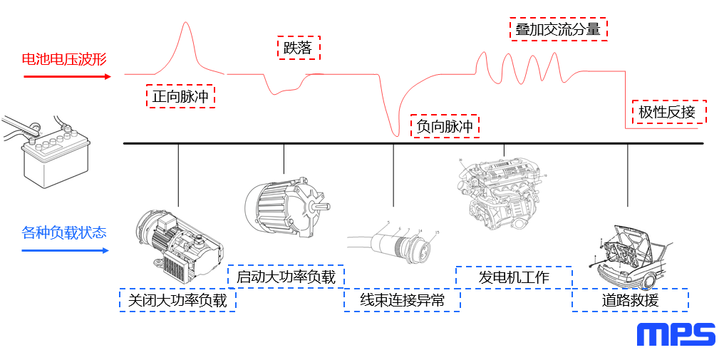
Figure 1: Pulse types in different application scenarios
To solve the various pulse interferences that may exist on the automotive power line, industry associations and major automobile manufacturers have developed relevant test standards to simulate transient pulses on the power line. These standards include ISO 7637-2 and ISO 16750-2, as well as the test standards of Mercedes-Benz and Volkswagen. As the most front-end circuit, the anti-reverse protection circuit must also meet industry test standards.
Anti-reverse protection circuit
There are three basic types of reverse protection circuits, as described below.
Series Schottky diode
This circuit is usually used for small current applications between 2A and 3A. The circuit is simple and low cost, but the power consumption is large.
PMOS in series on the high side
For applications with currents exceeding 3 A, PMOS can be placed on the high side. This drive circuit is relatively simple, but the disadvantage is that PMOS is more expensive.
When the power supply is positively connected, the PMOS channel is turned on, the tube voltage drop is small, and the loss and temperature rise are low.
When the power supply is reversed, the PMOS channel is turned off and the parasitic body diode realizes the anti-reverse protection function.
NMOS in series on the low side
This circuit requires an NMOS to be placed on the low side. A simplified gate drive circuit usually uses a cost-effective NMOS. The function of this circuit is similar to that of a PMOS placed on the high side. However, this anti-reverse protection structure means that the power ground and the load ground are separated, which is rarely used in automotive electronic product design.
Figure 2 summarizes these anti-reverse protection circuits.
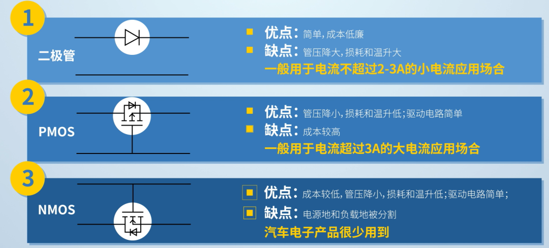
Figure 2: Types of anti-reverse protection circuits
This article will focus on the PMOS anti-reverse protection circuit.
PMOS
Most traditional reverse protection circuits use PMOS, whose gate is connected to ground with a resistor. If the input is connected to a forward voltage, the current flows to the load through the body diode of the PMOS. If the forward voltage exceeds the voltage threshold of the PMOS, the channel is turned on. This reduces the drain-source voltage (VDS) of the PMOS, thereby reducing power consumption. A voltage regulator is usually connected between the gate and the source to prevent overvoltage conditions on the gate-source voltage (VGS), and to protect the PMOS from breakdown when the input power fluctuates.
However, the basic PMOS anti-reverse protection circuit also has two disadvantages: large system standby current and reverse current. This will be described in detail below.
The system standby current is large
When PMOS is used in a reverse protection circuit, there is leakage current around VGS and the protection circuit (composed of a Zener diode and a current limiting resistor). Therefore, the current limiting resistor (R) has an impact on the overall standby power consumption.
The value of the current limiting resistor should not be too large. On the one hand, the normal clamping current of ordinary voltage regulators is basically mA level. If the current limiting resistor is too large, the Zener diode cannot be turned on reliably, and the clamping performance will be significantly reduced, resulting in the risk of overvoltage on VGS. On the other hand, too large a current limiting resistor means that the PMOS drive current is small, which will result in a slower on/off process. If the input voltage (VIN) fluctuates, the PMOS may work in the linear region for a long time (the MOSFET in this region is not fully turned on), and the resulting high resistance will cause the device to overheat.
Figure 3 shows the standby current in a conventional PMOS reverse protection circuit.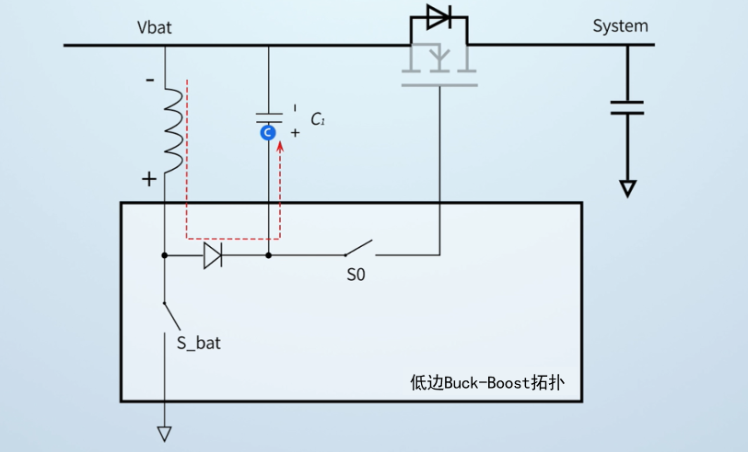
Figure 3: Standby current in a traditional PMOS anti-reverse protection circuit
There is reverse current
In the ISO 16750 input voltage drop test, the PMOS remains open circuit when VIN drops. In this case, the system capacitor voltage will reverse the power polarity, causing the system power failure and triggering the interrupt function. In the superimposed AC input voltage test, since the PMOS is completely open circuit, current will flow back. This will force the electrolytic capacitor to charge and discharge repeatedly, eventually causing overheating.
Figure 4 shows the input voltage drop test.
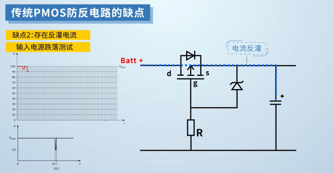
Figure 4: Input voltage drop test
- How to Build a Smart Knock Detection Door Lock Using Arduino
- DIY a practical audio-visual doorbell
- Production of two-color music lantern
- Ray detection circuit
- Four water tower control schematic diagram
- Ultrasonic humidifier circuit
- Infrared light controlled toy tank circuit
- EKG FM Demodulator Circuit
- Box type electronic mousetrap circuit
- Toy police car circuit
- Multivibrator composed of 555 timer
- Automatically set timer
- Overvoltage detection circuit
- Pulse silent operation total protector circuit c
- Pulse boost circuit a
- Qianhe 100Hz signal frequency pulse charging electric bicycle battery circuit
- Tianneng TN-1 intelligent negative pulse charging circuit
- One of the single-junction transistor trigger circuits that is not affected by power grid fluctuations
- Touch alarm circuit (2)
- Pulse, triangle wave and sawtooth wave signal generator circuit using 566 02


 京公网安备 11010802033920号