How to transfer electricity from the source to the energy storage system?
Source: InternetPublisher:兰博 Keywords: Electricity Energy Storage System Updated: 2025/02/25
Solar technology is booming, and its power generation is growing every year. However, how can the power be transferred from the source to the energy storage system (ESS) and then delivered to the load? This process is power delivery. In concept, this process is very simple, but in practice it is very complex. After all, the amount of power and the consistency of energy can change unpredictably at any time, and the system power level is not constant.
Available solar energy is precious. It is not enough to simply store the energy in batteries and then deliver it to the load through an inverter. First, the efficiency of collecting the energy must be high enough; then, the energy must be delivered to the energy storage subsystem through a high-quality controller. This article will provide an overview of power delivery and present some popular ESS methods.
- Energy Storage System
ESS consists of three main components (Figure 1):
The path between the energy source and the energy storage device; the energy storage device is usually a battery energy storage system (BESS), but it may take other forms
Energy storage devices and their management
DC/AC inverter between the energy storage device and the load (i.e. end user or grid)
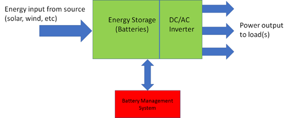
Figure 1: Batteries can receive and store electrical energy from a variety of sources and deliver it to loads as power through a DC/AC inverter (Image source: Mouser Electronics)
ESS can store energy and deliver it to the load as power when needed. Solar energy is an energy source that can only be supplied intermittently. This characteristic makes power resilience, which is key for applications such as homes and businesses, a major challenge. As an important medium to alleviate the intermittent problem of renewable energy, energy storage systems have emerged.
Batteries are becoming an excellent solution for energy storage due to the rapid growth of demand for advanced battery chemistries in electric vehicles (EVs). Energy storage batteries and their management systems between the energy source and the load must regulate the collected energy to meet the power supply demand.
- Capacity-driven architecture
There are so many combinations of energy sources and application loads that there is no single architecture that provides the best performance. In addition, solar-based photovoltaic (PV) devices are suitable for various market segments depending on the power size.
When it comes to solar energy, a common way to segment the market is to include three major areas:
Home use: Private spaces with power not exceeding 10kW
Commercial: Office buildings and factories requiring up to 5MW of power
Utilities: installed in the field, power over 5MW
- Factors to consider when scaling up solar power generation
Solar panels are made up of multiple individual photovoltaic cells, each of which can produce a single-digit voltage output. By connecting these panels in series, system designers can maximize the efficiency of the architecture and achieve the required power. As a result, the size of the solar power system can be more accurately mapped to the power for a specific application.
The following article will focus on PV BESS for residential or small commercial installations, as these are common applications that consumers are familiar with.
- How solar energy charges batteries
A major convenience of battery energy storage is that it can be used independently or integrated into the grid as a backup power source or to support power during peak hours (Figure 2).
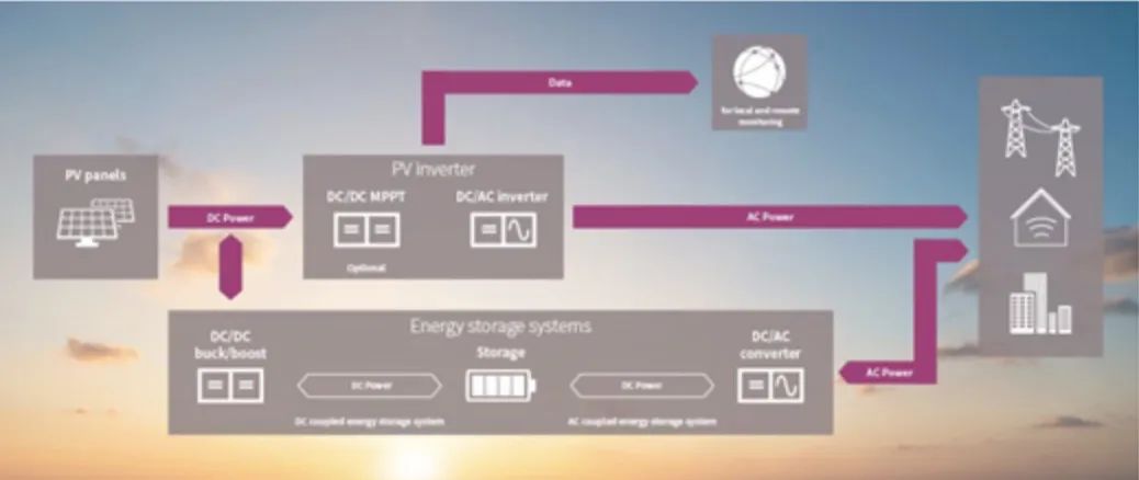
Figure 2: Block diagram of the key functions required for a complete solar energy storage system to supply power to local loads and the grid as needed (Source: Infineon Technologies)
The electrical interface between the PV panel and the battery is a DC/DC converter with buck, boost, or buck/boost characteristics. The type of converter the designer chooses depends on the comparison between the relative maximum voltage of the PV output and the maximum voltage of the battery array.
However, the ideal way to deliver power from solar panels is to use a charge controller, such as the Phoenix Contact AXC F 2152
PLCnext controller. This charge controller transfers the maximum power from the PV cell output first to the DC/DC converter and then to the energy storage battery at the maximum power point (MPP), when the power is matched to the load.
The AXC F 2152 controller is ideal for solar applications because it performs well in harsh environments.
The current produced by a solar cell is proportional to the amount of sunlight it receives, while its open circuit voltage remains relatively constant. The power output at the inflection point of each curve reaches its extreme value, at which point the cell switches from a constant voltage device to a constant current device, as shown in the power curve of Figure 3.
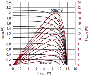
Figure 3: Solar panel power output is greatest when the cell is switched from a constant voltage device to a constant current device (Image source: Analog Devices)
MPP is a function of PV panel/solar characteristics and ambient temperature. When the sunlight intensity cannot support the full power requirement of the charger, a charger with an efficient design can adjust the output voltage of the solar panel to the maximum power point. This function can obtain more power output during the conversion process, thereby improving energy efficiency.
Therefore, to extract the maximum possible power output from a PV panel during use, engineers should monitor the MPP and panel load to control the converter and dynamically optimize power output (Figure 4). This behavior is called maximum power point tracking, or MPPT.
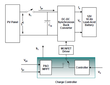
Figure 4: Basic MPP management (here for lead-acid batteries) requires adjusting the DC-DC converter as the load seen by the panel depends on the panel’s output
MPPT requires setting a strategy or algorithm in the charge controller to determine the MPP and then track it. Engineers can use two methods to track the maximum power: the constant panel voltage method and the disturbance observation method.
Constant Panel Voltage Method
The most straightforward tracking method is to set the panel voltage to a constant voltage level determined by the cell open circuit voltage (VOC) provided in the battery data sheet. Design engineers estimate the panel voltage at maximum power (VMP) at a fixed voltage just below VOC. To simplify this approach, the design team treats the temperature coefficient at VMP as equal to the temperature coefficient at VOC and as linear over the expected temperature range. These approximations allow the panel voltage to be set to VMP using a simple temperature compensation resistor.
Perturb and Observe (P&O)
The constant panel voltage approach has its drawbacks: it no longer provides much efficiency when conditions change, such as shifting cloud cover and normal wear and tear on PV components.
Another more advanced method that can accommodate MPPT tracking conditions is called "perturb and observe" (P&O). P&O
MPPT evaluates the slope of the power change versus the voltage change (ΔP/ΔV), which is positive to the left of the MPP, negative to the right of the MPP, and zero at the local maximum, which represents the ideal voltage. The dynamic MPPT algorithm maps any changes in the MPP by intentionally "perturbing" the panel load slightly above and below the normal value and then observing the changes in the output (whether good or bad).
The MPPT algorithm embedded in the controller achieves the highest possible efficiency in the process of collecting power from the battery and transferring it to the output, regardless of changes in environmental conditions such as radiation, dust and temperature. Once the controller completes the startup mode, it begins to execute the MPPT mode to search for the maximum power point. Figure 5 shows how the duty cycle of the pulse width modulation (PWM) signal changes to find the zero slope point in the curve.
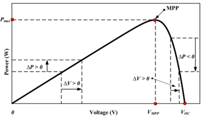
Figure 5: The MPPT method evaluates the power change slope and voltage change characteristics around the normal operating point of the photovoltaic panel (Source: SN Applied Sciences)
- Take out the power
Getting energy into the battery is only part of the BESS challenge. The system is designed to deliver the energy stored in the battery to the load, typically using a 120/240VAC line to power equipment and systems.
The output function requires a DC/AC inverter, which converts the battery's DC output into line-compatible AC. Like the electronics between the power source and the battery, the inverter is not a "one-size-fits-all" device. Engineers must consider the inverter's topology and design, as well as a number of design challenges and trade-offs. Although there is no formal definition, experts often divide inverters into three power and feature categories: low power, medium power, and high power.
Micro inverter (low power)
Low-power microinverters are rated between 50W and 400W, with individual inverters and MPP trackers integrated into each solar panel, and are more efficient than string inverters. Very little DC wiring is required, but a lot of AC wiring is required. Therefore, this type of inverter is only suitable for small systems.
Series inverter (medium power)
The string inverter is a medium power configuration that ranges from 1kW to 20kW. In this method, solar panels are connected in series with multiple inverters, usually one panel per string. This method is highly efficient because each set of string inverters can operate independently at a maximum power point.
Central inverter (high power)
Central inverters are high-power configurations, with power of 20kW and above. This method connects multiple sets of series inverters in parallel, using only one inverter for each set of solar panels. Because the voltages of each set of series inverters are different, engineers add special diodes to drive the panels to maximum power. However, diodes have inherent losses, which reduce efficiency. Therefore, the central inverter may not be able to drive all solar panels to the maximum power point.
- Conclusion
Renewable energy is bringing new opportunities for power control in areas such as intermittent power sources and power delivery architectures. Connecting solar panels to batteries with simple controllers and using the batteries for power may work occasionally, but there are also performance drawbacks, safety issues, and efficiency problems.
Instead, choosing the right controller and DC/DC topology on the energy-storage-battery management path will yield better results. Engineers should optimize the selected DC/DC inverter to ensure performance efficiency, consistency, long life, and resilience.
- How to ensure the stable performance of SSD when the voltage is unstable?
- Redundancy principle of power management system, a redundant design strategy in outdoor power BMS
- Single-power supply circuit for ISO122P/ISO124
- Transformerless AC-DC constant current LED driver circuit
- Offline 8w LED Flyback Power Supply with PFC using NCP1014
- LED rechargeable flashlight circuit diagram
- Parallel DC regulated power supply circuit diagram
- Current/voltage conversion circuit using current converter
- Power supply circuit that can reduce LM317 ripple
- Homemade low-power UPS
- Power circuit a composed of intelligent thyristor modules
- Laser power circuit
- Voltage stabilization control circuit in power circuit
- Warm current power supply circuit b
- Power circuit for home appliance repair
- Common power circuits and applications 03
- 25Hz ring current power supply circuit
- Always ready power circuit
- 5V, 7.5V, 48V power circuit
- CASPER TM-5158 VGA color display power supply circuit


 京公网安备 11010802033920号