Introduction to MCU GPIO Interface
Source: InternetPublisher:武林萌主 Keywords: MCU MCU GPIO Updated: 2025/02/14
Microcontrollers (MCUs) are widely used to control all types of electronic devices. MCUs consist of a CPU (central processing unit), memory, and additional circuits that implement various peripheral support functions.
The CPU operates by reading programs and following instructions: reading data, performing calculations and comparisons, generating other operations based on the comparison results, etc. The role of memory is not only to store data, but also the program itself.
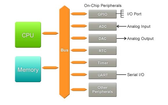
MCUs also include circuits that implement various peripheral functions, making it easier to deploy in a variety of settings. For example, an MCU typically includes a variety of I/O (input and output) ports to facilitate the flow of signals between the CPU and external sensors and switches. It also typically includes one or more ADCs (analog/digital converters) to convert incoming analog signals to digital values, and one or more DACs (digital/analog converters) to convert digital values to output analog signals. These I/O ports and converters support the use of a variety of signal types.
One of the most commonly used peripherals of microcontrollers is the RTC (Real Time Clock), which is used to achieve accurate time measurement and time monitoring and is widely used by processes that reference or depend on time. Another common peripheral is the UART (Universal Asynchronous Receiver Transmitter), which is used to convert parallel signals to serial signals and serial signals to parallel signals.
Important peripherals: GPIO interface
GPIO (General Purpose Input/Output) ports handle incoming and outgoing digital signals. As an input port, it can be used to communicate ON/OFF signals received from switches or digital readings received from sensors to the CPU. As an output port, it can drive external operations based on CPU instructions and calculation results - for example, driving an LED display based on calculation results, or outputting drive signals to a motor.
GPIO is also called a "general purpose interface" because each pin can be freely set to be used as an input or output. In early MCUs, each port was either exclusively input or exclusively output. However, GPIO is flexible. If it has 8 pins, you can set them to best suit your needs: 4 inputs and 4 outputs, or 7 inputs and 1 output, or any other combination.
It is important to note that when programs read, write, and manipulate digital values (0s and 1s), external devices typically use signal levels: low voltage and high voltage.
- What is serial communication of microcontroller?
- How to generate time delay using 8051 timer?
- How to use the GPS module of STM32F103C8 to obtain location coordinates
- How to build an Atmega16 based digital wall clock using DS3231
- How to Make a PIC Programmer
- Application circuit of CSJ-R05B and single chip microcomputer
- SN75370 Dual MOS Memory Interface Circuit
- Simple USB interface data acquisition system
- Interface circuit between 51 single chip microcomputer and MAX7219
- Ultrasonic anti-theft alarm designed based on microcontroller and HC-SR04
- PCF8591 hardware interface (circuit diagram pin diagram)
- Analysis of internal reset circuit diagram of microcontroller
- Negative voltage generation circuit diagram
- Design of infrared communication circuit based on single chip microcomputer
- Stepper motor drive circuit composed of LB1836M
- Minimum system interface circuit based on AT89C52 microcontroller
- IR2130 combined with microcontroller and SLE4520 for three-phase frequency conversion system diagram
- Use MC34063 as a 12-volt programming power supply for single-chip microcomputer
- Interface circuit between ICL7109 and microcontroller
- Monitoring of 8048 microcontroller by WMS7705


 京公网安备 11010802033920号