DIY a simple fire alarm
Source: InternetPublisher:念慈菴 Keywords: Sensors Fire Alarms Updated: 2025/02/11
When making fire alarms, we often use the method of sensor + microcontroller + buzzer. So, is there a way to realize a fire alarm with a simple circuit? Of course there is, and the cost is super low!
Let's look at the circuit diagram below. Transistor BC177 (Q1) is used here as a fire sensor. When the temperature increases, the leakage current of this transistor also increases. The circuit is designed so that when Q1
When the drain current of Q2 increases, transistor Q2 will be biased. Therefore, when a fire occurs, transistor Q2 will be turned on. The emitter of Q2 (BC 108) is connected to the base of Q3 (AC 128). Therefore, when Q2
When turned on, Q3 will also be turned on.
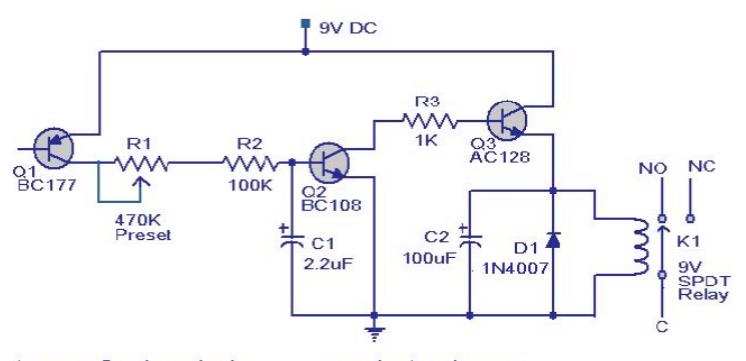
Transistor Q3 drives the relay, which is used to drive the load, i.e., lights, bells, horns, etc., as a fire indication. Diode D1
Used as a freewheeling diode to protect it from the back EMF generated when the relay switches.
Note:
(1) Preset R1 can be used to set the alarm to the desired temperature level.
(2) This is not a latching alarm, that is, the alarm stops when the temperature near the sensor drops below the set point.
(3) The circuit can be powered by a 9V battery or a 9V battery eliminator.
(4) All capacitors are electrolytic capacitors and must have a rated voltage of at least 10V.
(5) The load can be connected through the C, NC, and NO points of the relay as needed.
(6) You can use a soldering iron and a thermometer to calibrate. Turn on the power. Keep the soldering iron tip close to Q1. Also keep the thermometer close to it. When the temperature reaches the value you want, adjust R1 so that the relay turns on.
- Tutorial on making your own remote-controlled robotic arm
- Replace the GE LOGIQ a200 ultrasound measurement key with a self-made touch switch
- DC motor drive circuit composed of L293D
- Star-delta step-down starting control circuit for squirrel cage asynchronous motor
- Starting method of asynchronous motor with external frequency-sensitive resistor
- Design and production of radio remote control fan stepless speed regulator
- Design and analysis of a four-bit remote control component capable of remote reset
- Home wireless burglar alarm circuit
- Car audio system anti-theft circuit
- Bicycle anti-theft alarm
- X-Class CMOS sensor, do you know it?
- Remote Sensing Powered Sensing Amplifier
- heartbeat sensor
- Blood pressure sensing circuit diagram of BP01 pressure sensor
- Baby bedwetting voice alarm circuit
- signal processing circuit
- Circuit diagram for transmitting sensor signals
- Sensor bridge circuit diagram
- Basic connection diagram of bridge sensor and XTR104 02
- Connection circuit between sensor and A/D converter ADC614


 京公网安备 11010802033920号