Why should RS-485 transceivers be terminated? How to terminate?
Source: InternetPublisher:fish001 Keywords: Transceiver RS485 termination Updated: 2025/01/21
Many signal integrity and communication problems with RS-485 networks stem from termination, either due to lack of termination or improper termination. In this installment of the RS-485 Basics series, I will discuss when you do not need to terminate an RS-485 network, and how to use standard (parallel) termination and alternating current (AC) terminated networks when termination is required.
What I am going to explain in this article is that the 120Ω termination resistor value is derived from the differential characteristic impedance of the twisted pair bus. In short, the wire gauge, insulation type and thickness, and the number of twists per unit length all affect the impedance that the high-speed data signal "contacts." This impedance is expressed in ohms and typically ranges from 100Ω to 150Ω for twisted pair cable. The drafters of the RS-485 standard chose 120Ω as the nominal characteristic impedance, so to match this impedance, the default value for the termination resistor is also 120Ω.
The reason for the existence of termination networks
Matching the characteristic impedance of the cable to the termination network allows the receiver at the end of the bus to receive maximum signal power. Leaving the transmission line unterminated, or the termination value is not equal to the cable impedance, results in a mismatch that creates reflections at the end of the network. Reflections are exactly what the name implies, where some of the signal's energy returns to the line and then constructively or destructively interferes with the next bit traveling along the bus. A destructive example is if the reflected signal that bounces back is different from the input signal, causing the receiver to receive a smaller input signal. If the mismatch is severe, the reflected energy can cause subsequent bits to be misinterpreted and incorrectly decoded by the receiver.
Equation 1 shows that for the reflection coefficient to be close to zero, the input impedance ZL needs to match the source impedance ZS. If the load and source impedances differ greatly, almost the entire signal will be reflected.

As you can see, for excellent signal integrity, it is best to match the AC line impedance to an equal value termination impedance. Not all designers want to do this, why? Because adding termination networks increases the cost of the entire system, and these termination networks also add parallel loads to the driver, resulting in higher steady-state load currents. In power-sensitive applications where reducing power consumption is critical (such as in battery-powered applications), one option to save power is to not terminate the bus. Let's discuss when it is okay to not terminate.
Networks that do not require termination
One situation where a network does not need to be terminated is when the network's two-way round-trip time is much shorter than the 1-bit round-trip time (tbit > 10 times the two-way round-trip delay). In such a situation, reflections lose energy each time they reach the end of the network.
As can be seen in Figure 1, each time the signal reflects at the end of the cable, the amplitude of the reflection continues to decay. Figure 1 shows three round trips for the signal and a total of six reflections.
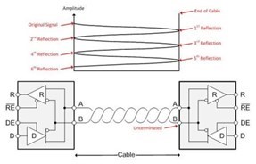
Figure 1: Reflection attenuation magnitude at each reflection
The estimated input impedance of the unterminated end of the bus is 96kΩ (one-eighth unit load), and the source impedance of the driver is 60Ω. Based on the calculations listed in Table 1, signal reflections will be attenuated.
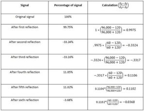
Table 1: Signal attenuation calculation example
As shown in Table 1, by the sixth reflection of the signal, it has attenuated to less than 4% of its original amplitude. After this point, it is safe to say that reflections will no longer cause signal integrity issues. Since the sample point for a bit typically occurs between 50-75% of the bit depth, you need to ensure that these three round-trip delays occur before the sample point.
Networks that require termination
For applications where the bit time is not significantly longer than the cable loop time, termination is critical in order to minimize reflections. The most basic termination network is called a standard or parallel termination network and consists of a single resistor (Figure 2).
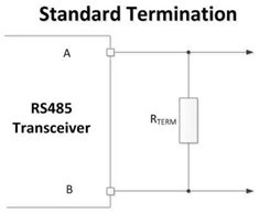
Figure 2: Standard termination network
With standard termination, you match the termination resistor value to the differential characteristic impedance of the cables at each end of the network. This ensures that the signals traveling in both directions on the bus are properly terminated. As I mentioned earlier, the main disadvantage of this type of termination scheme is that the resistor acts as a DC current to the driver as long as the driver is in operation.
(DC) load.
Using AC termination can help mitigate this power dissipation without requiring such long bit time requirements for bus lengths. Figure 3 shows an AC termination scheme.
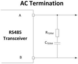
Figure 3: AC termination network
Since current normally flows from one side of an RS-485 driver through the termination network and then through the other side of the driver, the steady-state current can be driven to zero by placing a series capacitor. There are two caveats to this termination: it requires an additional component on each termination network, and the series resistor and capacitor introduce a resistance capacitance.
(RC) delay. The RC time constant slows down the rising and falling edges of the differential signal and limits the maximum data rate of the network.
Table 2 summarizes the three termination scenarios.
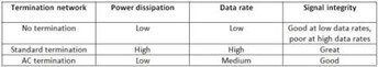
Table 2: Termination Technology Summary
For good signal integrity, it is best to match the differential characteristic impedance of the cable to the termination impedance of equal value. However, if you take the proper steps, you can successfully implement AC termination or avoid termination altogether.
- How to Build a Simple FM Radio Receiver on a Breadboard
- Analysis of the reasons why bow-tie antennas are preferred over microstrip antennas for 5G antennas
- MAX2820/MAX2821 I/Q 2.5-2.4 GHz Transceivers
- MAX23691/Q 2000-800 MHz Dual-Band Tri-Mode Transmitter
- RXM-900-HP-II FM/FSK 928~902 MHz Receiver Module
- XE1203 FSK 915/868/433 MHz Transceiver
- RF2909 GMSK/QPSK/DQPSK/QAM 915 MHz Transmitter
- CYWUSB6932 GFSK 2.4 GHz Wireless USB Interface Transmitter
- DKIOOOT OOK 315 MHz Transmitter Module
- RF2516 AM/ASK/OOK 433/315 MHz Transmitter
- 16-port 50GbE PHY transceiver, do you know it?
- TI TCAN4550 system basic chip analysis
- Photoelectric isolation RS485 typical circuit diagram
- Indoor unit communication circuit
- Ultra-low power transceiver network circuit with RS485 performance
- Circuit combining RS232 and RS485
- Long distance serial communication circuit
- Computer wireless data transceiver circuit diagram
- RS232-RS485 interface circuit
- CAN bus communication circuit


 京公网安备 11010802033920号