How to Make a Digital Taxi Meter Using Arduino
Source: InternetPublisher:宋元浩 Keywords: Display screen meter Arduino Updated: 2024/12/31
Today, digital meters are replacing analog meters in every field, whether it is electricity meters or taxi meters . The main reason is that the mechanical parts of analog meters are prone to wear out over time and are not as accurate as digital meters.
A good example is the analog speedometer and odometer used on older motorcycles to measure speed and distance traveled. They have special components called a pinion and rack arrangement where a cable is used to rotate the pin of the speedometer as the wheel rotates. Over time, these will wear out and also require replacement and maintenance.
In digital meters, instead of using mechanical parts, some sensors like photo interrupter or hall sensor are used to calculate the speed and distance. This is more accurate than analog meters and does not require long-term maintenance.
Today, in this tutorial, we will make a prototype of a digital taxi meter using Arduino. This project calculates the speed and distance travelled by the wheels of the taxi and displays it continuously on a 16x2 LCD display. When we press a button, it generates the fare amount based on the distance travelled.
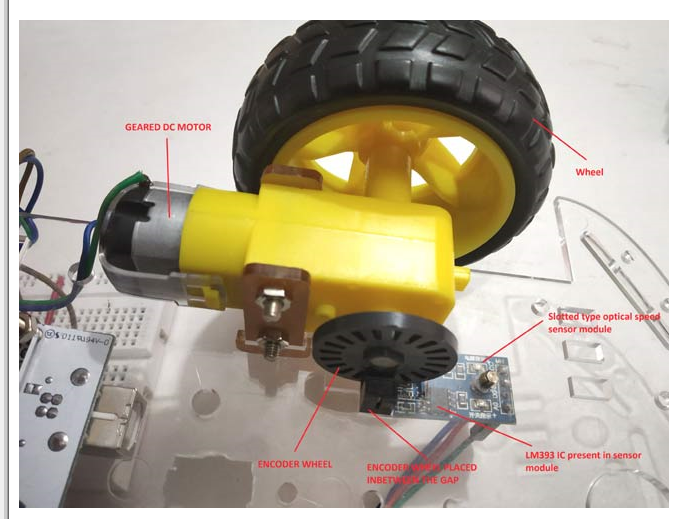
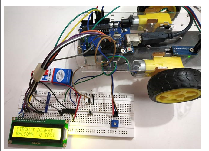
The following image shows the complete setup of Digital Taxi Meter project

This prototype has an RC car chassis with a speed sensor module and an encoder wheel attached to the motor . Once the speed is measured, we can measure the distance travelled and find the fare amount by pressing a button. We can set the speed of the wheel using a potentiometer. To know more about using LM-393 Speed Sensor Module in Arduino , follow the link. Let us see a short introduction of the Speed Sensor Module.
Infrared slotted optical LM-393 speed sensor module
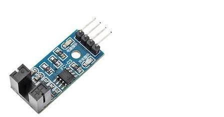
This is a slot type module which can be used to measure the rotation speed of the encoder wheel. This speed sensor module works on the basis of slot type photo interrupter also known as light source sensor. This module requires a voltage of 3.3V to 5V and produces a digital output. So it can be interfaced with any microcontroller .
The infrared light sensor consists of a light source (IR- LED) and a phototransistor sensor. There is a small gap between the two. When an object is placed between the gap of the IR LED and the phototransistor, it interrupts the light beam, causing the phototransistor to stop passing current.
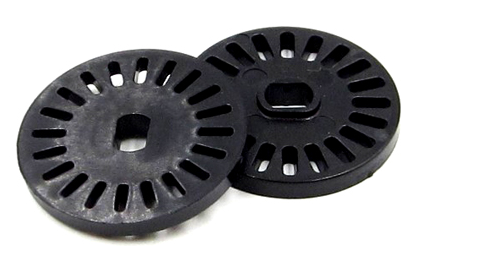
So for this sensor, a slotted disk (encoder wheel) is used which can be attached to the motor and as the wheel rotates with the motor, it interrupts the light beam between the IR LED and the phototransistor, thus switching the output on and off (generating pulses).
So, it produces a HIGH output when there is a break between the source and sensor (when any object is placed in between) and a LOW output when no object is placed. In the module, we have an LED to indicate the light break caused.
This module comes with LM393 comparator IC for producing accurate HIGH and LOW signals at the output. Hence this module is sometimes called LM393 speed sensor.
Measure travel speed and distance to calculate fares
To measure the speed of rotation, we need to know the number of slots present in the encoder wheel. I have an encoder wheel with 20 slots in it. When they rotate one full revolution, we have 20 pulses at the output. So, to calculate the speed, we need the number of pulses produced per second.
For example
If there are 40 pulses in one second, then
Speed = Noo. Pulses/slots = 40/20 = 2RPS (Revolutions per Second)
To calculate speed in RPM (revolutions per minute), multiply by 60.
Speed in RPM = 2 X 60 = 120 RPM (Revolutions Per Minute)
Measuring distance
Measuring the distance traveled by a wheel is very simple. Before calculating the distance, you should know the circumference of the wheel.
Wheel circumference = π*d
Where d is the diameter of the wheel.
The value of π is 3.14.
I have a wheel (RC wheel) with a diameter of 6.60 cm, so the circumference is (20.7 cm).
Therefore, to calculate the distance traveled, simply multiply the number of pulses detected by the circumference.
Travel distance = wheel circumference x (number of pulses / number of grooves)
Therefore, when a wheel with a circumference of 20.7 cm requires 20 pulses, that is, when the encoder rotates one circle, the distance traveled by the wheel is calculated by the following formula
Distance traveled = 20.7 x (20/20) = 20.7 cm
To calculate the distance in meters, divide the distance in centimeters by 100.
NOTE: This is a small RC car wheel, real car wheels are bigger than this. So I'm assuming a 230cm circumference for the wheel in this tutorial.
Calculate fares based on distance travelled
To get the total fare amount, multiply the distance traveled by the fare (amount/meter).
Note: In this tutorial, I have assumed a charge of Rs. 5 per meter.
So if the wheel travels 20m, the fare will be 20*5=100 rupees.
So now let's get the components and build the circuit.
Required Components
Arduino UNO
LCD display (16x2)
Button
Potentiometer - 10k
ULN2003 Motor Driver IC
LM393 Speed Sensor Module (FC-03)
RC Smart Car Chassis with Speed Encoder
Battery 9V
Breadboard
Connect the wires
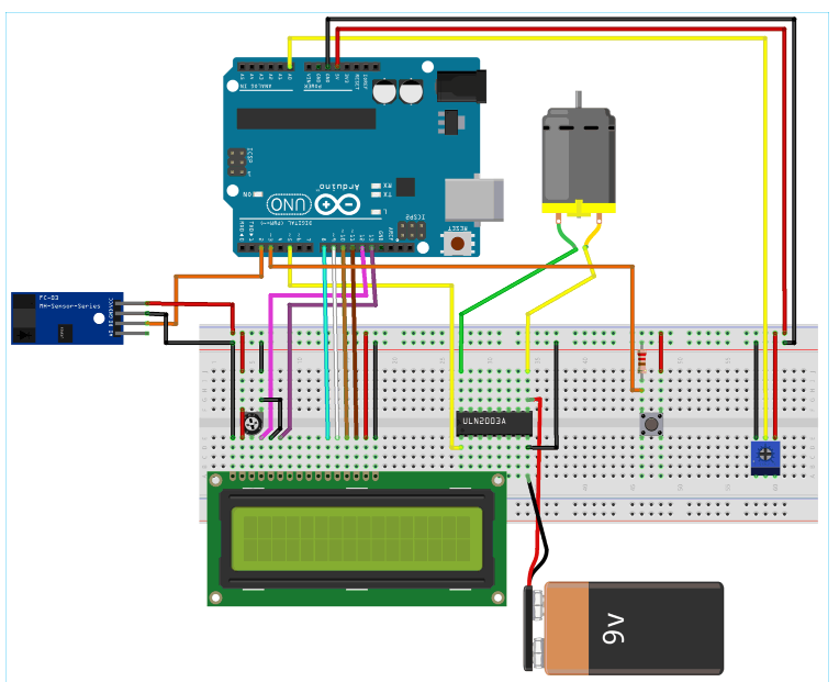
Circuit Schematic
The circuit diagram of the Digital Taxi Meter project using Arduino is shown below:
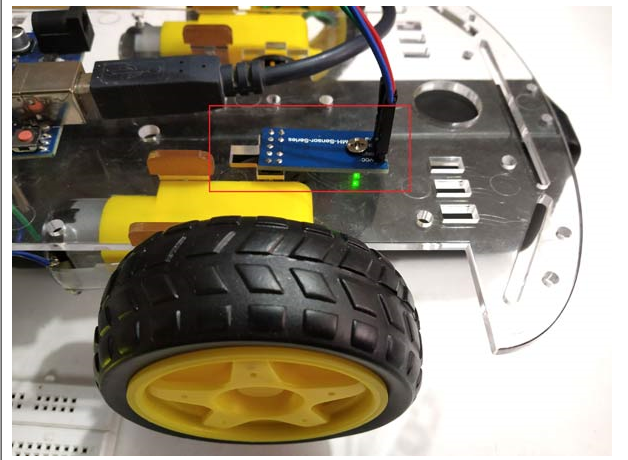
Installing speed sensor on remote control car chassis
The speed sensor is mounted on the encoder wheel between the sensor gap. In my chassis I have a special hole for placing the sensor. See the picture below
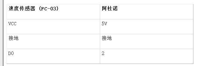
Connection between Speed Sensor Module and Arduino
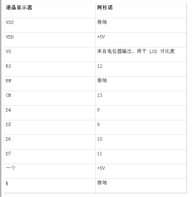
Connection between Arduino and 16x2 LCD
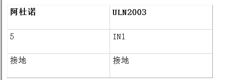
Connection between Arduino and ULN2003
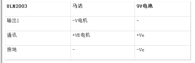
Connection between ULN2003, DC motor and 9v battery
I used a 9V battery and ULN2003 IC to power the motor externally.
Button and Potentiometer Connections
A push button with a pull-down resistor is connected to pin 3 of the Arduino to generate the fare amount when pressed.
The potentiometer is used to provide an analog input voltage to pin A0 of the Arduino to vary the speed of the motor wheel.
Programming an Arduino for a Digital Taxi Meter
The complete code with a demonstration video is provided at the end of this tutorial . Here we have seen several important parts of the code.
Before getting into the code, we need to understand the interrupts and TimerOne library used in the code.
Interrupt is used here because we need to keep checking the output detected at the speed sensor module as a high priority. So ISR is used in the code. ISR is Interrupt Service Routine which is called when an interrupt occurs at interrupt pins 2 and 3.
Arduino UNO has two interrupt pins 2 and 3.
At pin 2, connect the output of speed sensor D0.
At pin 3, a push button with a pull-down resistor is connected.
The TimerOne library is used in this code to check how many rotations (how many pulses) are detected in one second, from which we can calculate the speed per second and display it in the output. This ISR function is executed once per second
So let's look at our code in detail:
1. First, the library containing the functions to be used in the program.
#include "TimerOne.h"
#include
2. Next we declare global variables as they will be used throughout the program.
volatile unsigned int counter = 0;
volatile unsigned int rotation = 0;
float rotationinm = 0;
unsigned int speed = 0;
3. Next define and initialize the LCD pins connected to the Arduino.
const int
4. Next in void setup()
Define the pin mode, here pin A0 is used to get the analog input from the potentiometer and pin 5 is used to write the analog output connected to the IN1 pin of the ULN2003 IC.
pinMode(A0, INPUT);
pinMode(5, OUTPUT);
Next display some welcome messages and clear them.
  lcd.start(16,2); //Set LCD to 16x2 type
  lcd.setCurs
The next important part is setting up the interrupt pin and the ISR to be called when the interrupt occurs
First, we need to set timer1 to 1 second, and then attach an ISR to timer1 so that it is called once a second. The ISR name is timerIsr
Timer1.initialize(1000000);
Timer1.att
Next, two external interrupts are attached. The first interrupt makes Arduino pin 2 as an interrupt pin and calls the ISR (count) when RISING (LOW TO HIGH) is detected on pin 2. This pin 2 is connected to the D0 output of the speed sensor module.
The second one makes Arduino pin 3 as interrupt pin and calls ISR (generatefare) when a high level is detected on pin 3. This pin is connected to a push button via a pull-down resistor.
attachInterrupt(digitalPinToInterrupt(2), count, up);
attachInterrupt(digitalPinToInterrupt(3), generatefare, HIGH);
5. Next, let's take a look at the ISR we use here:
ISR1-count() ISR is called when a rise (from low to high) occurs on pin 2 (connected to the speed sensor).
void count() // ISR for speed sensor count
{
  counter++; // Increase the counter value
  A circle ++; //Increase the rotation value by one
  delay(10);
}
ISR2- timerIsr() calls ISR every one second and executes those lines present in ISR.
void timerIsr()
{
detachInterrupt(digitalPinToInterrupt(2));
Timer1.detachInterrupt();
lcd.clear();
float speed = (counter / 20.0) * 60.0;
float rotation = 230 * (rotation / 20);
rotationinm = revolutions/100;
lcd.setCursor(0,0);
lcd.print("Distance(m):");
lcd.print(rotation);
lcd.setCursor(0,1);
lcd.print("Speed (RPM):");
lcd.print(speed);
counter = 0;
int analog = analogRead(A0);
int motorspeed = map(This function contains the line that actually detaches Timer1 and Interrupt pin2 first because we have the LCD print statement in the ISR.
To calculate SPEED in RPM we use the following code where 20.0 is the number of slots preset in the encoder wheel.
float speed = (counter / 20.0) * 60.0;
And calculate the distance using the following code:
float rotation = 230 * (rotation / 20);
Here we assume that the wheel circumference is 230 cm (as this is normal for real-time cars)
Next convert the distance in meters by dividing it by 100
rotationinm = revolutions/100;
After that we display the speed and distance on the LCD screen
lcd.setCursor(0,0);
lcd.print("Distance(m):");
lcd.print(rotation);
lcd.setCursor(0,1);
lcd.print("Speed (RPM):");
lcd.print(speed);Important: We have to reset the counter to 0 because we need to get the number of plus signs detected per second, so we use this line
counter = 0;
Next it reads the analog pin A0 and converts it into digital values (0 to 1023) and further maps these values to 0-255 for PWM output (set speed of the motor) and finally writes these PWM values to the motor IC using analog write function connected to ULN2003.
int analog = analogRead(A0);
int motorspeed = map(analogip,0,1023,0,255);
analogWrite(5,motorSpeed);
ISR3: generatefare() ISR is used to generate the fare amount based on the distance travelled. This ISR is called when interrupt pin 3 is detected as high (when the button is pressed). This function separates the interrupt from pin 2 and the timer interrupt and then clears the LCD.
void generatefare()
{
   detachInterrupt(digitalPinToInterrupt(2)); Pin 2
   Timer1.detachInterrupt();
   lcd.clear();
   lcd.setCursor(0,0);
   lcd.print("Ticket Price Rs: ");
   float_rupee = rotation_inm * 5;
   lcd.print(Rs);
   lcd.setCursor(0,1);
   lcd.print("Rs. 5 per metre");
   }
After that, multiply the distance travelled by 5 (I have used 5 to represent the rate of Rs. 5/m). You can change this as per your wish.
float_rupee = rotation_inm * 5;
After calculating the amount value, it is displayed on the LCD display connected to Arduino.
   lcd.setCursor(0,0);
   lcd.print("Ticket Price Rs: ");
   lcd.print(Rs);
   lcd.setCursor(0,1);
   lcd.print("Rs. 5 per metre");
Complete code
#include "TimerOne.h" //Contains the Timer1 library that uses the Timer1 function
#include
- What is the LiFePO4 discharge curve? Advantages and applications of LiFePO4 discharge curve
- Build an Automatic Candy Vending Machine
- How to use Tesseract for optical character recognition on Raspberry Pi
- How to Make a Buzz Wire Game Using Arduino
- Using VPX-based PCIe systems for asynchronous clocking
- How to use RFID to create an automatic roll call attendance system
- How to build an internet-connected traffic meter
- Laser constant power control circuit
- Laser adjustable constant current drive circuit
- Test and Application of Power Amplifier TDA7294
- LED driver CAT3606 application circuit diagram
- Application circuit of CAT3606
- CAT3606 application circuit
- How does an optocoupler work? Introduction to the working principle and function of optocoupler
- 8050 transistor pin diagram and functions
- What is the circuit diagram of a TV power supply and how to repair it?
- Analyze common refrigerator control circuit diagrams and easily understand the working principle of refrigerators
- Hemisphere induction cooker circuit diagram, what you want is here
- Circuit design of mobile phone anti-theft alarm system using C8051F330 - alarm circuit diagram | alarm circuit diagram
- Humidity controller circuit design using NAND gate CD4011-humidity sensitive circuit


 京公网安备 11010802033920号