Small amplitude modulation transmitter
Source: InternetPublisher:zo8SWhbsr Keywords: AM transmitter Updated: 2025/12/19
Small AM transmitter
So, I needed a small transmitter to get my favorite old music onto my AM-only radio. So, one Saturday afternoon, I set to design and build a very rough, extremely unoptimized little transmitter. It's practically an electronic joke, riddled with terrible design, so please don't consider it the best I could do! You have to think of it as a quick, dirty 5-hour effort, because that's how much time it took to design, build, and test the transmitter. Creating this webpage about it took much longer! I'm putting this online simply because many people asked me to, despite its crude design!

If you've ever looked at the antique radio section of my website, you know I love restoring and listening to old radios from my grandfather's time. But those old radios only received AM! FM wasn't widespread yet. Today, on the contrary, FM's superior sound quality has almost completely driven AM stations out of the market in many parts of the world. Where I live, I still only receive three AM stations during the day (this was in 2006), which isn't many, considering the AM broadcast band can accommodate over 100 stations! Meanwhile, there are 31 FM stations… and worse, most of those three AM stations transmit programs that are simply not suitable for my beautiful old radio! I mean, it's such a waste to own an Atwater Kent tube radio, sitting in a pretty polished wooden cabinet, only to have it play modern pop or today's news!
This is a schematic diagram. You can click on it to get a full-resolution version for easy printing. As you can see, the transmitter couldn't be simpler: a TTL quartz oscillator provides a 1MHz square wave to directly drive the transistors in full-on switching mode. A tank circuit converts the square wave into an approximate sine wave, with a 50-ohm output taken from one-eleventh of the tank circuit's capacitive reactance.
The modulation section is equally simple: two input jacks hold stereo signals, which are simply added to form the mono signal needed by the modulation transmitter. A fine-tuning potentiometer allows adjustment of the modulation level. Setting it to the middle of the range will provide the correct modulation depth for line-level signals (like those offered by most CD players). An audio adder drives a power transistor, which modulates the supply voltage of the RF transistor. That's pretty much it… add a standard regulated 12V supply and an additional 6V regulator to bias the modulator and power the TTL oscillator, and that's the whole circuit.
If someone else had done this design, I would find plenty of criticism: the high resistance in the audio circuitry generates far more noise than strictly necessary, but it's still low enough for this application. The audio bandwidth limit given by C4 isn't fixed; it varies depending on the setting of R4. Terrible, but works well enough in practice…powering a 5V TTL circuit from 6V to 6V via a buck diode is a rather compromise, but hey, it's cheap, works, and allows me to use one of the many 7806 chips I have on hand! The transistor I'm using for RF is actually rated for UHF, a waste to use at only 1MHz! But again, I had one in stock, so I used it…of course, starting with never regulated 20V, regulated to 12V, then setting the modulator's bias point halfway down that level, and then resistor-coupled the RF power transistor, resulting in the transmitter consuming about 5 watts from the AC line while only providing about 50mW of RF output! That's 1% efficiency…but I certainly won't criticize it, since I made this thing!
I'm sure I've done a better design at other times. But it works good enough, so what! Here it is, feel free to use it or skip it! :-)
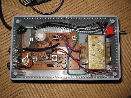
The transmitter is housed in a plastic project box and uses a perforated board instead of a printed circuit board. While a printed circuit board would certainly be more elegant, designing and fabricating one would increase construction time by at least five times!
The RF transformer is actually a 455kHz intermediate frequency transformer salvaged from a discarded transistor radio from the 1970s. I removed its internal 470pF capacitor. With the addition of an external 100pF capacitor, it can easily tune to 1MHz. The higher impedance winding must have approximately 250 microhenries, and the turns ratio of the low impedance winding is approximately 1:10.
The 7812 voltage regulator is mounted on a heatsink. Other components do not require any heatsinks, and even the 2SC1173 gets quite hot.
I'm using RCA jacks for audio input and RF output. You can certainly use other connectors if you prefer. A shielding box would be nice, but not really necessary. After all, you want this thing to radiate a signal!
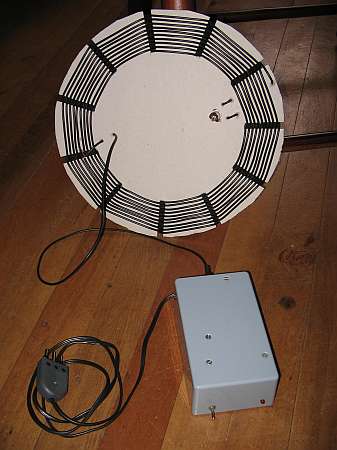
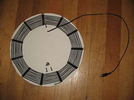
The antenna is a resonant multi-turn loop. It has 19 turns of ordinary household multi-strand wire wound around a sturdy cardboard with 11 slits cut into its edge. Why 11? Well, 10 or 12 would sound better, but we need an odd number so we can create a low parasitic capacitance winding! The wire passes through each slit, altering the side of the cardboard, and to avoid all the turns touching adjacent turns, the number of slits must be odd.
The cardboard disc has a diameter of 30cm and a slit length of 5cm. This makes the innermost diameter 20cm and the outermost diameter approximately 28cm.
The coil is tuned in parallel with a fixed capacitor via a nice old Philips air-dielectric trimmer capacitor. This capacitor is connected across the two ends of the coil. The feed is mounted on a single turn, with the shield positioned exactly in the middle of the coil (midpoint of the 10th turn) for optimal balance. A small coaxial cable (RG174 or standard audio shielded cable) is mounted through holes punched in the cardboard for stress relief. The trimmer capacitor is also mounted through the board.
The tuning system is simple: First, you connect a load resistor of about 50 ohms to the transmitter and tune T2 to obtain the highest signal. You can measure this with an oscilloscope, or with a simple RF probe and multimeter. Then you connect the antenna and tune its trimmer capacitor to obtain the maximum signal. The two sides of the trimmer capacitor are hot on RF, so use an insulated tool, or tune in small increments with your fingers, removing your hand between them to eliminate hand-introduced detuning. You can measure the signal at both ends of the feed tap, or with a pickup loop placed close to the antenna. When tuning, there will be about 5V on each turn, so a single turn placed close to the antenna (10cm is close enough) will pick up about 5V RF, which is easy to measure.
The antenna's natural Q-factor is above 300, so it would be too high to allow a full 10kHz wide amplitude modulation signal to pass through! Therefore, I fed the antenna through a full turn. This damped it significantly, resulting in an overall Q-factor of nearly 60. This is great for achieving sufficient bandwidth while strongly suppressing the rather strong harmonics generated by the transmitter. The RF signal picked up from the antenna is very clean, while the signal entering the dummy load from the transmitter is anything but clean.
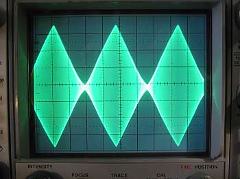
This is a screenshot of the picked-up signal, modulated with a triangle wave to the point where distortion begins. Up to 80% modulation, the transmitter is highly linear. As modulation is increased further, the distortion becomes visible on the oscilloscope and audible on the radio! I recommend setting R4 to 80% modulation for the highest audio peak. You can do this using an oscilloscope or by ear, adjusting R4 to get the highest possible modulation without audible distortion.
The antenna radiates only a fraction of the 50mW the transmitter can provide. When tuned, the antenna's input impedance is much higher than 50 ohms, causing a significant mismatch with the transmitter. This is perfectly fine, given the transmitter is fully anti-VSWR (thanks to R6), and considering the transmitter's purpose is simply to send a signal to a radio in the same household! For that, you don't need more than about one milliwatt of effective radiated power. The system does a great job. At a distance of 6 meters between the transmitting antenna and a 1935 tube radio, the received signal is about as strong as two of the three strongest local AM stations I can receive. Outside my house, the signal quickly becomes undetectable.
A quick tip: Before you consider replicating this transmitter, make sure you don't have any local AM radios transmitting at or near 1.000MHz! If you do, you'll have to find a quartz oscillator for a different frequency in the broadcast band, which is likely much harder than finding a 1MHz oscillator! In that case, it might be better to consider using a completely different drive source.
- FM radio using TDA7000
- BH1417 USB FM Transmitter
- 250mW FM VHF transmitter
- 1.5V tracking transmitter
- BH1417 Phase-Locked Loop FM Transmitter
- 1-watt FM transmitter
- The simplest FM microphone circuit diagram (wireless microphone circuit diagram)
- 9018 single-tube FM transmitter circuit diagram
- Illustrated diagram of two basic transistor UHF radio transmission circuits
- FM transmitter circuit made with TA7335 integrated circuit
- USB communication circuit
- Indoor unit communication circuit
- Two-way communication circuit circuit diagram
- Long distance serial communication circuit
- CAN bus communication circuit
- Wireless transmitter circuit diagram
- Time division multiplexing stereo decoder circuit
- Design of wireless transmitting and receiving circuit based on Bluetooth
- Fiber optic transceiver circuit diagram
- Square wave generation circuit


 京公网安备 11010802033920号