Lead-acid battery charger circuit
Source: InternetPublisher:GemRBw0T0u Keywords: Battery charger Updated: 2026/01/06
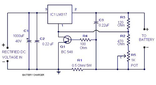
Lead-acid battery charger circuit
This is a lead-acid battery charger circuit using the LM317 integrated circuit. This IC provides the correct charging voltage to the battery. The battery must be charged at 1/10 of its ampere-hour value. This charging circuit is designed based on this fact. The battery charging current is controlled by Q1, R1, R4, and R5. Potentiometer R5 can be used to set the charging current. When the battery is charging, the current through R1 increases.
This changes the on-state of Q1. Since the collector of Q1 is connected to the adjustment pin of IC LM317, the output voltage of LM317 increases. When the battery is fully charged, the charger circuit reduces the charging current; this mode is called trickle charging mode.
Note: Connect the battery and ammeter in series in the circuit. Now adjust R5 to obtain the required charging current. Charging current = (1/10) * battery ampere-hour value. The IC input must be at least 15V to obtain 12V for charging the battery. Please refer to the LM317 datasheet for better understanding. Install a heatsink for the LM317.
- Lithium polymer battery charger
- 30V/4A Adjustable Desktop Power Supply
- Power LED driver circuit
- USB-powered AA NiMH/NiCd battery charger
- A classic linear 5V power supply using a 6.3V AC transformer.
- Charging monitor for 12V lead-acid batteries
- High-current regulated power supply based on LM317
- Lithium-ion and lithium-polymer charger circuits
- Solar cell charger based on LM317
- How to Determine Bandwidth from Transient Response Measurements
- Motorcycle battery charger circuit
- Two specifications of nickel-cadmium battery charger circuits
- Dry battery charger circuit
- Gel battery charger circuit
- Single junction transistor battery charger circuit
- Nickel-cadmium battery charger circuit with voltage and current limiting function
- Portable nickel-cadmium battery charger circuit
- Portable nickel-cadmium battery charger circuit
- battery charger
- Battery charger circuit diagram with discharge function


 京公网安备 11010802033920号