A classic linear 5V power supply using a 6.3V AC transformer.
Source: InternetPublisher:hEgQA8tz9m Keywords: Transformer rectifier regulated power supply Updated: 2026/01/13
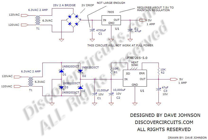
Below is a classic method for generating a regulated +5V DC power supply. The circuit consists of a core transformer, a bridge rectifier, a filter capacitor, and a voltage regulator. Many people tend to use the very popular 6.3V transformer to make this +5V power supply, but they often find that, except under very light load conditions, the transformer voltage is insufficient for the circuit to function properly. Higher transformer voltages can work, but at the cost of more power being consumed in the voltage regulator.
Most transformers are specified for a 120VAC input. At 110VAC, a 6.3VAC transformer might only output 5.8VAC. To ensure operation under almost all reasonable conditions, I often design circuits to function even at line voltages as low as 105VAC. In this case, the 6.3VAC from the transformer might only deliver 5.5VAC.
Using a typical bridge rectifier and filter capacitors will not provide sufficient peak voltage to ensure good regulation. However, not all hope is lost. This classic transformer design can still be used, provided you choose the right components.
First, a traditional bridge rectifier can be replaced with four power Schottky diodes. A typical bridge rectifier using standard silicon diodes will have a voltage drop of about 2 volts, while a Schottky diode bridge will only drop by one volt. Although this is not much, it does help. Next, the size of the main filter capacitor can be increased to reduce the ripple voltage across it. One way to calculate the ripple voltage is to use the equation: dv/dt = I/C. dv/dt is the voltage change across the capacitor. I is the DC load current, and C is the capacitance. For a 60Hz power line, the value of dt is 0.008 seconds. For a 50Hz power line, a value of 0.010 seconds is used.
Therefore, if we choose a large 20,000uF capacitor with a current of 1 amp, the ripple voltage (dV) will be approximately 0.40V at 60Hz and 0.50V for a 50Hz system. At 105VAC, the transformer secondary is 5.5VAC. The peak voltage is 1.41 × 5.5V, or 7.7V. Subtracting the 1V from the Schottky bridge and the 0.40V from the ripple voltage, you are left with 6.3V DC as the input to the voltage regulator. This is only 1.3V higher than the required 5V, but it should be sufficient if you use a regulator with low input-output voltage drop. I recommend the National Semiconductor LP3872ES-5.0 voltage regulator. This device requires only about 5.3V on the input side to maintain 5V at the output with a 1-amp load. In my design, I recommend using a 6.3VAC transformer rated at 2 amps and two large 10,000uF filter capacitors at the bridge output. Although the voltage drop across the regulator is small, I recommend mounting the regulator on a heatsink rated for approximately 5 watts.
- 12V to 28V DC-DC converter (based on LM2585)
- 1.2-36V 5A Adjustable Power Supply (Based on LM317)
- LM317 power supply circuit
- 24V to 12V 400W DC-DC converter
- Power LED driver circuit
- Atmel solar panel battery charger
- Charging monitor for 12V lead-acid batteries
- DC 13.8V to DC 250V inverter circuit
- Shaver power circuit
- How to simulate our buck converter control loop?
- Things to note when selecting an inductor
- Transformer overtemperature alarm circuit
- Y, y connected transformer lightning protection wiring
- Commonly used non-sinusoidal oscillator circuits, waveforms and frequency calculation formulas - pulse wave oscillator - transformer intermittent oscillator
- Automatic switching control circuit for two parallel transformers
- Simple buzzer circuit three
- Switching power supply drive transformer EE-18
- Transformer output power amplifier circuit diagram
- Transformer tap regulator
- 30W feedback transformer switching power supply circuit diagram


 京公网安备 11010802033920号