Power LED driver circuit
Source: InternetPublisher:gPgVeB Keywords: LED driver circuit Updated: 2026/01/23
Power LED driver circuit
Here is a very simple and inexpensive power LED driver circuit. This circuit is a "constant current source," which means that it can maintain a constant LED brightness regardless of what power supply you use or what environmental conditions you place the LED in.
Or in other words, "this is better than using resistors." It is more consistent, more efficient, and more flexible. It is particularly suitable for high-power LEDs and can be used with any number and configuration of ordinary or high-power LEDs, and with any type of power supply.
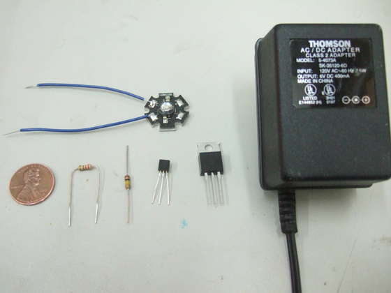
As a simple project, I built a driver circuit and connected it to a high-power LED and a power brick to create a plug-in light. Power LEDs are around $3 these days, so this is a very inexpensive and versatile project that you can easily modify to use more LEDs, batteries, etc.
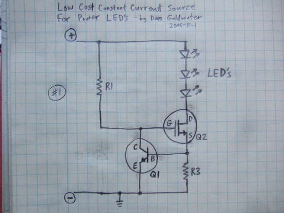
Circuit components (refer to schematic diagram)
R1: Approximately 100 kΩ resistor (Yageo CFR-25JB series)
R3: Current setting resistor - see below
Q1: Small NPN transistor (Fairchild 2N5088BU)
Q2: Large N-channel FET (Fairchild FQP50N06L)
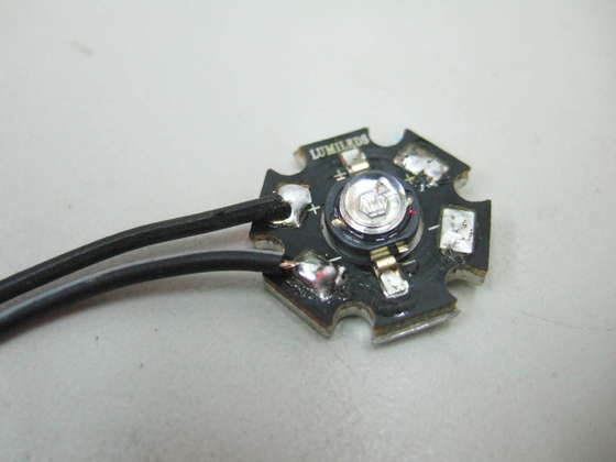
LED: High-power LED (Luxeon 1-watt white LED LXHL-MWEC)
Other components:
Power supply: I used an old wall-mounted transformer, but you can use batteries. Powering a single LED will require any 4 to 6 volt power supply with sufficient current. That's why this circuit is so convenient! You can use various power supplies; it will always light up in the exact same way.
Heatsink: Here I built a simple lamp with no heatsink at all. This limits the LED current to about 200mA. For higher currents, you will need to place the LED and Q2 on a heatsink (see my notes in other power LED guides).
Prototype board: I didn't use a prototype board initially, but later built a second one on top of it. There are some photos at the end if you want to use the prototype board.
Select R3:
This circuit is a constant current source, and the value of R3 sets the current.
calculate:
- The LED current is set by R3, and it is approximately equal to: 0.5 / R3
- R3 power: The power consumed by the resistor is approximately: 0.25 / R3
I used a 2.2-ohm resistor R3 to set the LED current to 225mA. R3 has a power rating of 0.1 watts, so a standard 1/4-watt resistor will suffice.
Here I will explain how the circuit works and its maximum limitations; you can skip this if you wish.
Specification:
Input voltage: 2V to 18V
Output voltage: Up to 0.5V lower than input voltage (0.5V voltage difference)
Current: 20 amps or more, with large heat sink
Maximum limit:
The only real limitation of the current source is Q2 and the power supply used. Q2 acts as a variable resistor, reducing the supply voltage to match the LED's demands. Therefore, if the LED current is high or the supply voltage is much higher than the LED string voltage, Q2 will require a heatsink. With a large heatsink, the circuit can handle a significant amount of power.
The specified Q2 transistor is designed for a maximum supply voltage of approximately 18V. If you require higher voltages, please refer to my LED circuit guide for details on how the circuit needs to be modified.
Without a heatsink at all, Q2 can dissipate only about 1/2 watt before it gets very hot – enough for a 200mA current and a voltage difference of up to 3 volts between the power supply and the LED.
Circuit function:
- Q2 is used as a variable resistor. Q2 is initially turned on by R1.
- Q1 is used as an overcurrent detection switch, and R3 is a "sensing resistor" or "setting resistor" that triggers Q1 when the current is too high.
The main current flows through the LED, Q2, and R3. When too much current flows through R3, Q1 will turn on, thus turning off Q2. Turning off Q2 reduces the current flowing through the LED and R3. Therefore, we have created a "feedback loop" that continuously tracks the current and keeps it at the setpoint.
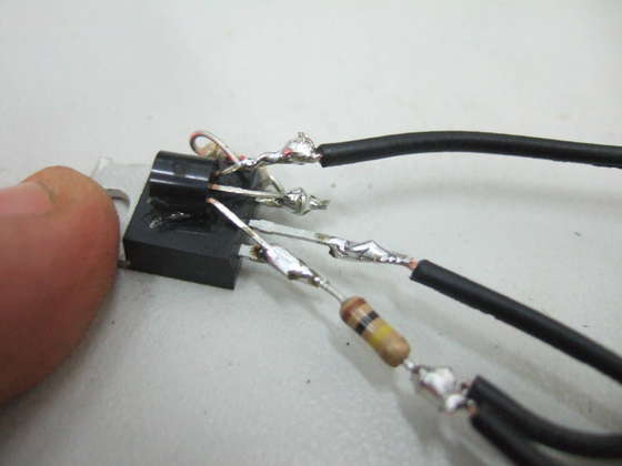
This circuit is very simple, and I will build it without a circuit board. I will simply connect the leads of the components in the air! But if you prefer, you can use a small prototype board (see the photo at the end as an example).
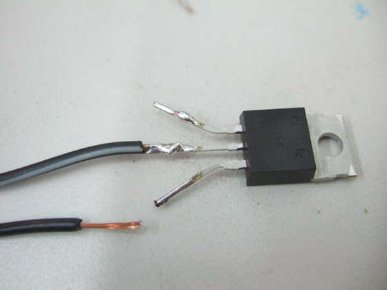
First, identify the pins of Q1 and Q2. Place the part in front of you with the label facing up and the pins facing down, with pin 1 on the left and pin 3 on the right.
Comparison with schematic diagram:
Q2:
G = Pin 1
D = pin 2
S = pin 3
Q1:
E = pin 1
B = Pin 2
C = Pin 3
Therefore: First, connect the wire from the negative terminal of the LED to pin 2 of Q2.
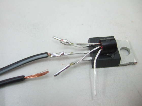
We will now begin connecting to Q1.
First, attach Q1 upside down in front of Q2 for easier handling. This also has the added benefit of causing Q1 to lower its current limit if Q2 gets very hot – a safety feature!
Connect pin 3 of Q1 to pin 1 of Q2.
Connect pin 2 of Q1 to pin 3 of Q2.
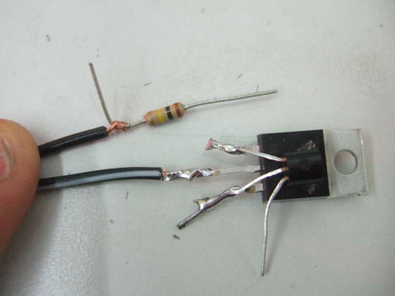
Solder one leg of resistor R1 to the suspended positive lead of the LED.
Solder the other leg of R1 to pin 1 of Q2.
Connect the positive terminal of the battery or power source to the positive terminal of the LED. In practice, it might be easier to do this first.
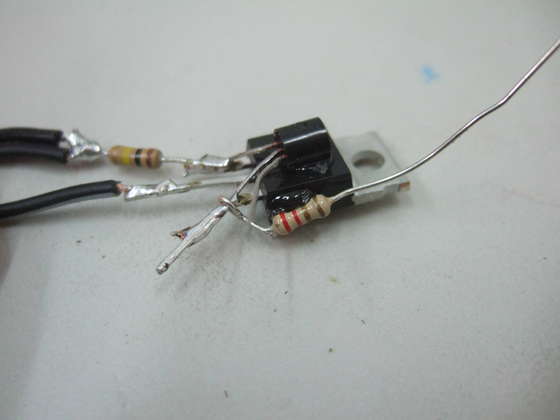
- Attach R3 to the side of Q2 to secure it.
Connect one lead of R3 to pin 3 of Q2.
Connect the other lead of R3 to pin 1 of Q1.
Now connect the negative power supply wire to pin 1 of Q1.
You're done! We'll make it even stronger in the next step.
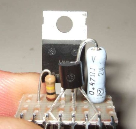
Now test the circuit by applying power. Assuming it works, we just need to make it durable. A simple way is to coat the entire circuit with a large amount of silicone. This will make it mechanically strong and waterproof. Just apply the silicone and try to remove any air bubbles. I call this method "BLOB-TRONICS". It doesn't look like much, but it works very well and is cheap and simple.
Additionally, binding the two wires together can help reduce stress on the wires.
I've also added a photo of the same circuit, but on a prototype board (this one is "Capital US-1008", available at Digikey), and using 0.47 ohms resistor R3.
- Full-range adjustable power supply
- LM317 Adjustable Regulated Power Supply
- Automatic battery charger
- RGB LED driver
- A classic linear 5V power supply using a 6.3V AC transformer.
- Power Soft Start
- USB Lithium Polymer Battery Charger
- Five Easy Steps to Powering Your SoC with a PMIC
- How to simulate our buck converter control loop?
- Re-examining the importance of current power monitors
- DC 12V to AC 100V inverter power supply circuit design
- Portable device charging power circuit design
- 2-phase CPU power circuit using HIP6301 and HIP6601 chips
- Single phase thyristor slotless nickel plated power circuit
- 500A-6V single-phase thyristor voltage regulating electroplating power supply circuit
- led drive power circuit
- Household emergency power circuit 02
- Application circuit diagram of NCP5602 and NCP5612
- Common power circuits and applications 04
- Common power circuits and applications 02


 京公网安备 11010802033920号