PIC temperature recorder
Source: InternetPublisher:CBqMdW Keywords: PIC microcontroller temperature recorder Updated: 2026/01/13
PIC temperature recorder
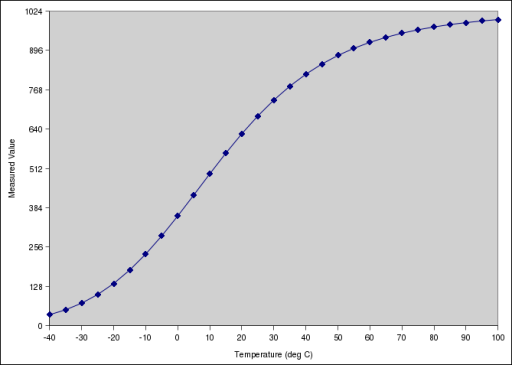
This project uses a Microchip PIC microcontroller, a serial EEPROM, and a thermistor to create a temperature logger. Temperature is measured and stored at user-programmable intervals; this can range from 1 second to 256 seconds. The time interval is set by programming it and a start time into the EEPROM. Most of the time, the PIC will be in sleep mode, and the EEPROM IC will be inactive. This results in very low current consumption, approximately 50 microamps or about 1 milliamp-hour per day. The EEPROM used is 32 kilobytes and can store up to 32,000 measurements. For example, this could be a measurement every 30 seconds for 11 days. The combination of the thermistor and analog circuitry provides a range of approximately -40°C to +100°C, although the linear range is between approximately -10°C and +40°C.

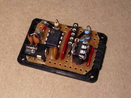
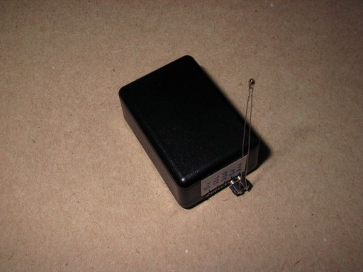
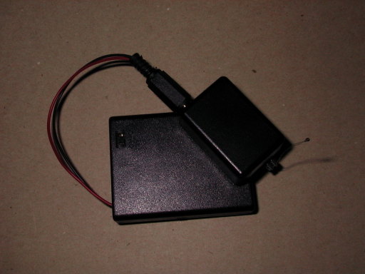
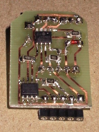
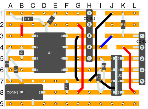
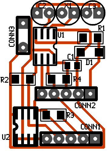
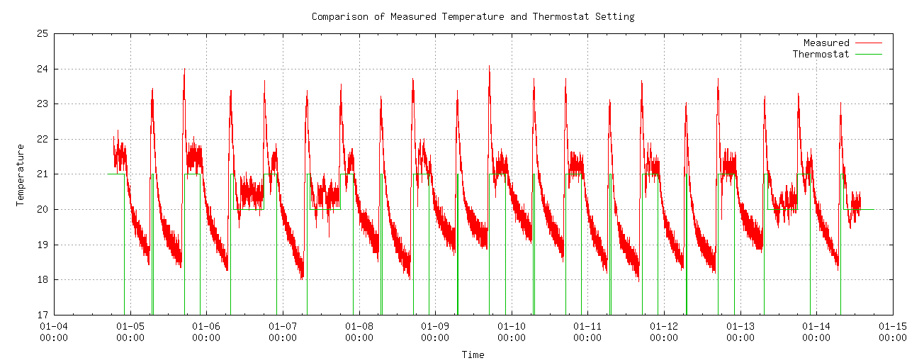
In this image, you can see the temperature logger plugged into an external thermistor. The connectors at the end contain power, I2C clock and data, and analog inputs. The overall dimensions of the complete unit are 40 mm long, 26 mm wide, and 16 mm high. The box with the battery compartment is also shown in this image; the temperature logger is connected to a battery pack with four AAA batteries. This nicely illustrates the dimensions and shows that a smaller battery pack is needed. PCB (Version 1): The first version of the circuit, PCB Version 1, is built on a stripboard using DIL-packaged ICs and conventional through-hole passive components. The PIC microcontroller is located on the center left of the PCB, and the EEPROM IC is vertically mounted on the center right to save space. The external connectors are a 1.3 mm power socket in the lower left corner and a 5-pin SIL socket on the right. Other components include an ICSP socket (with resistor and diode) in the upper left corner, a crystal oscillator and two capacitors to the left of the PIC, two I2C pull-up resistors next to the EEPROM, and a thermistor voltage divider resistor in the upper right corner. PCB (Version 2) The second version of the circuit is built on a custom-made single-sided PCB, using SO8 packaged ICs and surface-mount passive components. The ICs are pitched to only 0.05 inches (1.27 mm), the decoupling capacitors are 0805 packages (0.08 inch x 0.05 inch = 2 mm x 1.27 mm), and the resistors are 1206 packages (3 mm x 1.5 mm). The crystals and their capacitors are the same as before, as are the connectors. All traces are routed at 0.02-inch widths (0.5 mm), although they are slightly wider in final production. Software PIC Software The PIC software is written in assembly language, based on an earlier project using an I2C interface. The EEPROM, PIC, and external connectors share the same I2C bus, which the PIC does not use unless a thermistor is installed. In this case, the EEPROM address is continuously incremented so that interrupts in the data can be seen. When no temperature measurement is being performed, the PIC enters sleep mode. It is woken up once per second (using an external crystal oscillator and an internal counter) to check if it is time to perform a measurement. The sampling interval is stored in a fixed location in an external bit EEPROM and read upon power-up. A thermistor and a resistor form a voltage divider, which is measured by an ADC channel on the PIC. This is measured four times, and the four results are added together. Due to noise present in the circuit, the average of the four readings may be closer to the true value than a single measurement, thus giving a slightly better measurement. The ADC measurement is stored directly, rather than first being converted to temperature. To save space and maintain accuracy, the change from the previous measurement is stored in 1 byte if possible, otherwise in 2 bytes. If the value changes from the previous measurement to between -112 and +112, the change is stored. If the value changes beyond this range, two bytes are stored, the first byte with a flag bit to indicate this. The PIC is a 12F683 device, operating at 4 MHz using an internal oscillator. The I2C interface operates at nearly 100 kHz using bit smashing (programmable control I/O lines), instead of the PIC SSP interface. Complete information for this project is available for download. This includes library functions for the I2C interface, as well as circuit diagrams, layout diagrams, and various C programs. This project is included in the downloadable PIC code library. To reset the device, the PC software has a program that erases the entire EEPROM (to 0xff) and writes a 32-byte header containing the time and sampling interval. The PIC will use the sampling interval to determine when to take a measurement; the start time is used by the program that extracts the data. To read data from the PIC, software dumps the entire EEPROM contents and extracts the start time, step size, and raw data. The data is converted into date, time, measurement value, and temperature for each data point in the EEPROM. The circuit diagram is very simple, including only an ADC interface (one resistor), an I2C interface (two resistors), an EEPROM IC, an ICSP (socket, one diode, and one resistor), and an oscillator (crystal and two capacitors). Circuit Layout Version 1: Circuit Layout on a Strip Board This simple PCB layout shows the placement of components on a strip board. The view is from the top of the PCB, the same as in the photograph. Circuit Layout Version 2: Circuit Layout on a Custom PCB This PCB layout shows the components and traces on a custom PCB. The view of the PCB is from the side with the traces, although some components are mounted on the other side. All the parts for this project are readily available, although surface-mount components are less common than standard components. Example Results: The image below shows example results obtainable using this device. Captured Temperature Data: The temperature logger was placed next to a household thermostat for approximately 10 days during the early winter of 2007. The graph shows the measured temperature and thermostat settings (a "smart" thermostat designed to reach a target temperature within a specified time). The measured data clearly match the thermostat settings during heating activity, with the temperature dropping rapidly during inactivity, both day and night.
- DAC0832 pin diagram and interface circuit
- Direct current voltage regulated power supply made by single chip microcomputer 89C51
- Why does a single-chip microcomputer need an external crystal oscillator? Crystal oscillator working principle and circuit diagram analysis
- How does MCU handle interrupts? MCU interrupt processing process
- What is grounding in microcontroller circuits?
- What is the difference between RISC-V, ARM and x86 microprocessors?
- What is the difference between a microcontroller and a microprocessor?
- Introduction to the use of UnoArduSim
- Improved circuit diagram of 8050 transistor emitter drive relay
- Application circuit of CSJ-R05B and single chip microcomputer


 京公网安备 11010802033920号