Why does a single-chip microcomputer need an external crystal oscillator? Crystal oscillator working principle and circuit diagram analysis
Source: InternetPublisher:公子李 Keywords: MCU Oscillator Crystal Updated: 2025/02/18
An oscillator (commonly known as a crystal oscillator) is a type of electronic circuit or electronic device that is mainly used to generate periodic oscillating electronic signals. The electronic signal generated by an oscillator is usually a sine wave or a square wave, and its function is to convert a DC signal into an AC signal. For example, radio and television transmitters use signals generated by oscillators for widespread broadcasting, and electronic buzzers and video game sounds are all generated by oscillator signals.
Why do microcontrollers need to use external crystal oscillators?
Generally, we know that a crystal oscillator is used in a microcontroller (MCU) to provide a clock signal. Let's consider the 8051 microcontroller, for which an external crystal oscillator circuit of 12MHz is necessary, even though the 8051 microcontroller is capable of running at 40MHz. The 8051 requires 12 clock cycles for one machine cycle, which provides an effective cycle rate of 1MHz (considering a 12MHz clock) to 3.33MHz (considering a maximum 40MHz clock). This crystal oscillator is used to generate the clock pulses required for synchronization of all internal operations.
There are different types of oscillator electronic circuits such as linear oscillators - Hartley oscillators, phase shift oscillators, Armstrong oscillators, Clapp oscillators, Colpitts oscillators, etc., relaxation oscillators - Royer oscillators, ring oscillators, multivibrators, and voltage controlled oscillators (VCOs).
In this article, we will discuss in detail about crystal oscillators such as what are crystal oscillators, crystal oscillator circuits, working principles and uses of crystal oscillators in electronic circuits.
1. What is a crystal oscillator?
An electronic circuit that produces an electrical signal of a precise frequency by exploiting the mechanical resonance of a vibrating crystal made of piezoelectric material. There are different types of piezoelectric resonators, but typically quartz crystals are used in these types of oscillators. For this reason, these oscillator electronic circuits are called crystal oscillators.
2. Crystal Oscillator Circuit Diagram
The quartz crystal oscillator circuit diagram can be represented as follows:
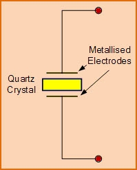
The figure above shows the electronic symbol of a piezoelectric crystal resonator, which consists of two metallized electrodes and a quartz crystal.
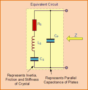
The figure above shows the equivalent circuit diagram of a quartz crystal in an electronic oscillator, which consists of a resistor, an inductor, and a capacitor connected as shown.
3. Working Principle of Crystal Oscillator
Atoms, molecules, ions are stacked in order in three spatial dimensions with a repeating pattern to form a solid that can be called a crystal. By using appropriate electrical sensors, a crystal can be made from almost any object made of elastic material. Since every object contains an inherent resonant frequency of vibration, steel has a high speed of sound and is very elastic.
Therefore, steel is often used instead of quartz in mechanical filters. This resonant frequency depends on different parameters such as size, elasticity, speed of sound and shape of the crystal. Usually, high frequency crystals are in the shape of simple rectangular plates, while low frequency crystals are in the shape of tuning forks.
The crystal oscillator circuit works on the principle of the inverse piezoelectric effect, i.e. mechanical deformation is produced by applying an electric field to certain materials. It thus exploits the mechanical resonance of a vibrating crystal made of piezoelectric material to produce an electrical signal of a specific frequency.
These quartz oscillators are very stable, have good quality factor, are compact and very economical. Hence, quartz crystal oscillator circuits are preferred over other resonators like LC circuits, forks etc. Usually, microprocessors and microcontrollers use 8MHz crystal oscillators.
The equivalent circuit also represents the crystal action of the crystal. The basic components used in the circuit, inductor L1 represents the mass of the crystal, capacitor C1 represents the flexibility, resistor R1 represents the internal structure friction of the crystal, and C0 represents the capacitance formed due to the mechanical shaping of the crystal.
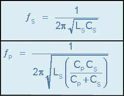
The quartz crystal oscillator circuit diagram includes series resonance and parallel resonance, that is, two resonant frequencies. If the reactance generated by capacitor C1 is equal to the reactance generated by inductor L1, series resonance occurs. The series resonant frequency and parallel resonant frequency are represented by fs and fp respectively, and the values of fs and fp can be determined using the following formula shown in the figure below.
Therefore, in this case, the impedance is approximately equal to the resistor R1. If the reactance of the series resonant leg is equal to the reactance due to capacitor C0, then parallel resonance will occur. Therefore, in this case, the external circuit if provided by the crystal presents a very high impedance.
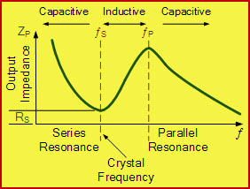
The figure above shows the relationship between impedance and frequency of a quartz oscillator circuit. Typically, the frequency range of a crystal oscillator is 32KHz to 200MHz.
- Tutorial on using 8051 microcontroller to display content on LCD screen
- How to control a bidirectional DC motor using an 8051 microcontroller
- How to build an Atmega16 based digital wall clock using DS3231
- Application circuit of CSJ-R05B and single chip microcomputer
- Interface circuit between intelligent temperature sensor TCN75 with two-wire serial interface and 89C51 single-chip microcomputer
- Using 89C2051 to make a four-way digital display water level controller circuit
- Digital frequency meter made with ATmega8 microcontroller
- How to use ESP8266 to design a portable air quality monitoring station
- Sharing the process of making a single-chip integrated digital clock
- USB-serial port conversion circuit made with CP2102 chip
- SPI interface and microcontroller interface principle circuit diagram
- Interface circuit design of SPCE061A microcontroller and fingerprint identification module
- FM radio high frequency amplification and mixing circuit
- 7-tube superheterodyne radio circuit
- How to connect the load of the capacitive three-point oscillator a
- Local oscillator and equivalent circuitb
- The interface between DAC1231 and microcontroller 8031
- Interface between serial IO port AD converter and microcontroller
- SMC62T3 microcontroller basic line connection
- Communication between 8031 microcontroller and PC-1500 computer


 京公网安备 11010802033920号