LM386 audio probe amplifier
Source: InternetPublisher:HnfErhw Keywords: Audio probe amplifier Updated: 2025/11/18
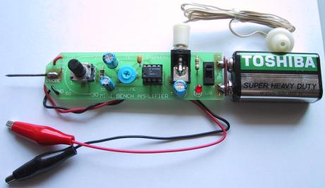
The LM386 audio probe amplifier is an essential tool for troubleshooting audio-related circuits, including amplifiers, oscillators, function generators, telephone circuits, radios, and many other projects. It's a very convenient test device that can be built onto pre-drilled boards, making it a perfect addition to your electronics collection. Audio stages can have many problems. They can produce distorted or "hollow" sounds, become weak, or fail completely.
Similarly, tone circuits can malfunction in many ways, and being able to "hear" where the problem is is very convenient.
Measuring the DC voltage of these stages alone is insufficient. This only provides partial information and doesn't tell you the quality of the audio being processed. To determine this, you need a testing device that allows you to see or hear what's being processed. Some items you can test with a mini benchtop amplifier are tone circuits, while others are audio circuits. Tone circuits and audio stages are surprisingly difficult to test unless you have audio probes or an oscilloscope. An oscilloscope is the ideal device, but if your budget is limited, an audio probe is the next best option.
First, we'll discuss the advantages and disadvantages of using an oscilloscope. The main problem with viewing waveforms on an oscilloscope is that you have to interpret what you see and determine if there's distortion and where it's coming from. Believe me, it's harder than you think. Let me give you an example from a TV repairman friend. He repaired approximately 35,000 TVs over 15 years, and during that time, he used an oscilloscope numerous times to try and find audio-level faults.
A particularly troublesome audio problem occurred on an old black and white television, so he took out an oscilloscope to try to solve the problem.
The audio was weak and distorted, but because the signal around the intermediate frequency transformer was very small even when the circuit was working properly, he was unable to locate the fault.
Circuit diagrams rarely display audio waveforms, making it difficult to tell whether the signal you're seeing on your oscilloscope is faulty or normal.
To repair the television, he had to resort to the old-fashioned, reliable method of replacing components one by one. The problem turned out to be an open circuit in a 100pF Styro capacitor in the audio intermediate frequency tank, which was reducing audio quality. However, the oscilloscope did not detect it.
On other occasions, he tried using an oscilloscope, but with the same result. It didn't really help.
If you are a highly qualified audio technician and know what waveforms you should get at each location, the situation will be completely different compared to trying to find unknown faults in the audio level. Sometimes, when viewed on an oscilloscope, the audio waveform looks very messy, but the audio is quite clear. Other times, the waveform looks quite good, but the signal is distorted.
If an oscilloscope is the answer to these problems, I would not hesitate to recommend that you buy one, but sometimes it can create more problems than it solves.
To generate an audio waveform suitable for viewing on an oscilloscope, you must inject a stable waveform into this stage, such as from a function generator or a sine wave oscillator. You cannot simply provide a signal from a radio station because the signal amplitude and frequency will vary. The oscilloscope will not be able to "lock in" and produce a stable waveform.
You cannot work on a constantly moving display. Such displays are only suitable for entertainment purposes at science exhibitions. The screen must be completely still so that you can view and take measurements.
You need to measure the output and compare it with the input.
This is where dual-trace oscilloscopes come in handy. On such an oscilloscope, you can display the input and output simultaneously by overlaying them. You can then see the differences.
Alternatively, you can display one waveform on top of another and highlight the differences.
If you only have a single-trace oscilloscope, you need to switch between the input and output as quickly as possible to detect differences.
Even if you see a difference, you must determine whether it represents a malfunction.
Audio distortion isn't always caused by clipping or overdrive; sometimes it's due to coupling capacitors being too small or dried out, making the sound "hollow" or "harsh." These types of faults won't be detected on an oscilloscope, so I recommend saving your money at this stage and building an audio probe instead.
It will enable you to fix audio glitches very easily and save you a lot of frustration.
LM386
The LM386 is a high-power operational amplifier. It is used to drive speakers. The inverting input is connected to the negative power rail, and the non-inverting input is connected to a capacitor. Internal resistors provide bias to this input, so only about 7mV is needed for the chip to turn on. This voltage is called the offset voltage.
When a signal is applied to the "+" input, the chip amplifies the waveform, and the result appears on pin 5. The chip's gain depends on the impedance of the path between pins 1 and 8. We have placed a variable impedance between these pins, consisting of a 22uF capacitor and a 10kΩ potentiometer; by changing the resistance of the potentiometer, the chip's gain will be adjusted.
The gain can be adjusted from 30 to 200, and these numbers are displayed on the board's overlay.
Repair audio level
As mentioned earlier, audio levels can have many problems. Sometimes they develop over time, or they may be present from the moment the amplifier is assembled. You may also experience intermittent malfunctions, dropouts, howling, jet ski noises, distortion, or simply a lack of gain.
The amplifier described in this article is used as an audio probe to listen to the loudness and quality of the audio entering the test stage and compare it with the audio that appears at the output of that stage.
You do this by bringing the earpiece close to your ear and listening carefully—that's why the probe has two long leads.
We could write a book about audio-level restoration, but to cut it to one page, here's how:
The simplest case is a single-transistor amplifier with output distortion.
The first thing to do is replace the transistor. Although transistors are very reliable devices, you may have overheated it, which will cause the device to have different gains, so the voltage on the stage will not allow the signal to be processed correctly (if this is not the cause of the problem, you can put it back later).
Next, the collector voltage is measured. Ideally, it should be half the supply voltage. This allows the transistors to turn on and off at maximum capacity, thus giving the stage maximum gain.
To conduct any further investigation into this stage, you will need a copy of the circuit diagram. This will show you how the transistors are biased and may provide detailed information about the voltages at each location.
Next, let's look at electrolytic capacitors. These can be interstage devices, decoupling capacitors, or emitter bypass capacitors. They may dry out and lose capacitance or become open-circuited (very rare) or short-circuited (very rare). Tantalum capacitors may also short-circuit because they are susceptible to high-voltage spikes that can puncture their ceramic substrate.
If a transistor has an emitter bypass capacitor in the form of an electrolytic capacitor across the emitter resistor, the stage gain will be severely reduced if the capacitor (electrolytic) loses its capacitance (dries out).
A faulty interstage capacitor (the capacitor connecting the output of one stage to the input of the next stage) can be checked by placing a probe on one side of the capacitor and then on the other side. If the audio level drops significantly and the capacitor is not transmitting a signal, it may be faulty.
If you replace the transistor with another type, the collector voltage may differ from the specified value.
If it is low, the transistor has a high gain, and the base bias resistor must be increased. If it is higher than expected, the base bias resistor must be decreased.
This only applies to simple self-biased stages, where the base bias resistor sets the collector voltage of the stage.
Resistors rarely have problems unless they are old-fashioned or located in a hot spot.
If a buzzing sound is present in the audio, the fault lies in the power supply filtering. If a whistling sound, similar to feedback howling (as heard when the microphone is too close to the amplifier speaker), is present, the fault is likely in the decoupling capacitor. This is typically a small electrolytic capacitor (10uF to 100uF), located near the stage it protects, and connected to a low-value resistor on the power rail. The electrolytic capacitor is connected across the power rail.
This electrolytic capacitor can also cause malfunctions similar to the putt-putt-putt problem in a motorboat's exhaust system.
The probe amplifier has a volume control in the form of a gain control to change the output volume from the earpiece. Approximate gain is indicated around the control.
An additional probe can be connected to the board via a small socket, which will allow the mini amplifier to be placed close to your ears so you can monitor the audio.
If it doesn't work
Turn on the audio probe and set the gain control to maximum. Touch the active probe with your finger. You should hear a slight hum from the speaker. This is a quick test to show the project is working. If nothing is detected, you should follow these steps:
If the power LED is not lit, the most likely reason is that the battery is dead or the battery terminals are not making contact.
Also check the placement of the LEDs, as they may be facing the wrong direction.
Next, check the current drawn by the circuit across the switch (with the switch in the OFF position). It should be approximately 10mA.
If the earbuds are not making a sound, use a multimeter to measure their resistance. When you do this, it should produce a slight "click" sound and measure about 8 ohms.
Check that pin 1 of the IC is close to the cutout on the cover layer and see if all pins of the chip are in the socket. Sometimes pins are bent and not making contact. Also ensure that all pins of the socket are soldered to the board. This applies to all other components. Finally, ensure that the positive terminal of the battery is connected to the positive power rail on the board and the negative terminal is connected to the negative power rail.
There are almost no other areas where things could go wrong, and the project should be working now.
Using an audio probe
All you need to do is connect the ground wire to the project you are testing, turn on the audio probe and the project you are testing. Use the probe or active leads to probe various points on the project under test and listen for audio. The gain control on the audio probe is very similar to the volume control, allowing you to hear the audio without overdriving it.
Most amplifier stages have a gain of around 50-70. Some have a gain of around 100, but that's the highest you'll get.
It's impossible to determine whether a stage has high or low gain simply by listening. The only way to calculate the gain factor is to use a CRO (cathode ray oscilloscope).
A clever fault-finding method is to obtain another identical unit and compare them.
To do this, you need to place both side by side and connect the ground wires together. Turn both on, and then you can probe each level and compare them.
If you've ever been frustrated trying to diagnose audio levels, you'll find this project absolutely essential.
- Speaker protection and mute
- Stereo code multiplexer
- USB Audio Digital-to-Analog Converter
- LM3876 Gain Cloning Amplifier
- LM3886 monaural amplifier
- Guitar Faz effects pedal
- Class A push-pull tube power amplifier
- High-fidelity tube amplifier
- TDA1551 audio amplifier circuit diagram
- LM4819 audio power amplifier circuit diagram
- Precision current detection amplifier design based on lithium battery detection
- High performance broadband GaN power amplifier
- volumeter
- New speaker coupling circuit diagram
- High input impedance three op amp differential amplifier circuit diagram
- A crystal controlled local oscillator circuit diagram
- non-diode rectifier
- Oscilloscope converter provides four channel display
- intercom circuit
- voltage amplifier circuit


 京公网安备 11010802033920号