Active low-pass filter design
Source: InternetPublisher:mG4k0t6 Keywords: low-pass filter Updated: 2026/02/24
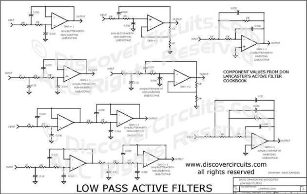
This is a collection of inverting and non-inverting active low-pass filter circuits. I have included first-order, second-order, third-order, fourth-order, and sixth-order filter circuits.
You can change the component value ratios shown to achieve any cutoff frequency you might need. No operational amplifier is specified for this circuit. These circuits are used to select the resistors and capacitors needed for a specific frequency inflection point and roll-off slope.
Latest Analog Circuits Circuits
- Active low-pass filter design
- Working principle of filter capacitors, importance of capacitor filters in bridge rectifier circuits
- How to Enhance the Performance of a Basic Low-Pass Filter
- Broadband low noise amplifier circuit
- Single-phase full-wave rectification π-type filter circuit
- AC multi-purpose amplifier circuit
- Differential input-differential output circuit
- High speed logarithmic amplifier circuit
- Precision low cost isolation amplifier IS0122
- Amplifier for measuring tiny currents
Popular Circuits
- Working principle diagram of bidirectional thyristor trigger circuit
- Analysis and design of AC amplifier circuit composed of integrated operational amplifier
- Two-stage resistor-capacitor coupling amplifier circuit
- Integrating circuit-precision rectifier circuit diagram
- Biased push-pull power amplifier circuit
- Bridge rectifier circuit diagram and current reversal
- Commonly used low pass filter circuit d
- Commonly used low pass filter circuit c
- Low-pass filter circuit composed of op amp
- Fourth-order 10KHZ low-pass filter circuit diagram


 京公网安备 11010802033920号