Transistor circuit diagram explanation
Source: InternetPublisher:newrudeman Keywords: Transistor analog circuit circuit diagram explanation Updated: 2021/01/14
Figure 1 shows the common emitter circuit of the NPN transistor. Figure 2 shows its characteristic curve. In the figure, it has three working regions: cutoff region (Cutoff Region), linear region (Active Region), and saturation region ( Saturation Region). The triode uses the B pole current IB as the input to control the working state of the entire triode. If the transistor is in the cut-off area, IB approaches 0 (VBE also approaches 0), the C pole and the E pole are approximately in an open circuit state, IC = 0, VCE = VCC. If the transistor is in the linear region, the BE junction is forward biased, the BC junction is reverse biased, the value of IB is moderate (VBE = 0.7 V), IC =h FEIB is proportionally enlarged, Vce = Vcc -Rc I c = V cc - Rc hFE IB can be controlled by IB. If the transistor is in the saturation region, IB is very large, VBE = 0.8 V, VCE = 0.2 V, VBC = 0.6 V. Both junctions BC and BE are forward biased, and CE is equivalent to a junction with a potential difference of 0.2 V. path, we can get I c = ( Vcc - 0.2 )/ Rc , Ic has nothing to do with IB, so the IB at this time is larger than the IB value of the linear amplification area, Ic

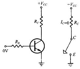
Figure 1 NPN transistor common emitter circuit Figure 2 Common emitter circuit output characteristic curve


Figure 3. The cut-off state is like a broken line diagram. Figure 4. The saturated state is like a path.
Experiment: switching function of triode
Simple transistor switch: The circuit is as shown in Figure 5. The resistor RC is a resistor for LED current limiting to prevent excessive voltage from burning out the LED (light-emitting diode). Adjust the input signal VIN from 0 to the maximum (divided into about 20 intervals), and observe And record the VOUT and LED brightness. When the transistor switch is open circuit, VOUT =VCC =12 V, and the LED does not light up. When the triode switch is on, VOUT = 0.2V, the LED will light up. Improved triode switch: Because the triode needs to pass through the linear region from the cut-off region to the saturation region, the switching effect will not have a clear boundary. In order to make the effect of triode switching clear, two triodes can be connected in series. The circuit is shown in Figure 6. Also adjust the input signal VIN from 0 to the maximum (divided into about 20 intervals), observe and record the corresponding VOUT and LED brightness.

Figure 5. Simple switching transistor circuit diagram
It can be seen from the above that almost any type of triode can be used as an electronic switch. If conditions permit, it can also be used to control heating equipment. It can be seen that switching transistors are only a general concept, but there are also a few dedicated switching transistors on the market.
- Signal diode arrays/configurations, freewheeling diode operation
- Symbol/working principle/type/characteristics/application scenarios of depletion-mode MOSFET
- What is a pure resistance circuit? What is a pure resistance AC circuit?
- How does sand become chips?
- RC filter explained in detail
- Why Do Amplifier Fuses Blow? How Do You Prevent Amplifier Fuses from Blowing?
- Ceramic filter structure/working principle/characteristics/application
- Experimental circuit based on 4040 binary adder counter
- Star finder battery indicator circuit
- Digital number selection machine
- Transistor circuit diagram explanation
- 3V-5V level conversion circuit diagram
- Short circuit protection electronic circuit diagram
- H-bridge drive circuit schematic diagram and enable control and direction logic
- Improved connection method of triode switch circuit circuit diagram
- Wireless microphone circuit diagram composed of 9018 triode
- Mixing circuit
- Precision regulated power supply circuit for UJ-1 type potentiometer
- One of the boiling water alarm circuits
- Flash signal light circuit 7


 京公网安备 11010802033920号