RC filter explained in detail
Source: InternetPublisher:同住地球村 Keywords: Test system RC filter Updated: 2025/01/14
In the test system, RC filter is usually used. Because in this area, the signal frequency is relatively low. RC filter has the advantages of simple circuit, strong anti-interference, better low-frequency performance, and the use of standard resistance and capacitance components. Therefore, the most commonly used filter in the field of engineering testing is RC filter.
5.1 First-order RC low-pass filter
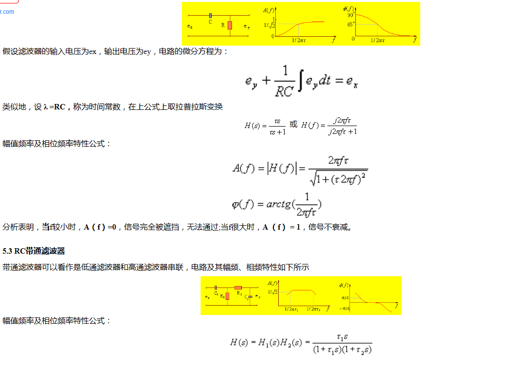
The amplitude and phase frequency characteristics of the RC low-pass filter circuit are shown below

5.2 First-Order RC High-Pass Filter
The RC high-pass filter circuit and its amplitude and phase frequency characteristics are shown below
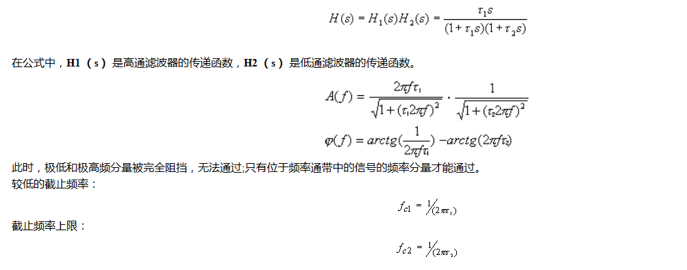
5.3 RC Bandpass Filter
The bandpass filter can be regarded as a low-pass filter and a high-pass filter in series. The circuit and its amplitude-frequency and phase-frequency characteristics are shown below.
It should be noted that when the high-pass and low-pass two stages are connected in series, the interaction between the two stages should be eliminated, because the latter stage becomes the "load" of the former stage, and the former stage is the signal source internal resistance of the latter stage. In fact, in fact, the two-stage common emitter follower is isolated by an operational amplifier. Therefore, the actual bandpass filter is usually active. The active filter consists of an RC tuning network and an operational amplifier. The operational amplifier can not only play the role of isolation, but also play the role of amplifying the signal amplitude.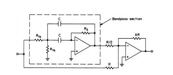
- What is the function of a voltage regulator in a circuit? How to connect a voltage regulator?
- Signal diode arrays/configurations, freewheeling diode operation
- What does a rectifier do? What is the process of rectification?
- How does a series arrangement of Zener diodes affect the electrical behavior?
- What is an ac to dc transformer in circuit design
- How do Zener diodes protect circuits?
- Causes of PCB deformation How to prevent circuit board bending and warping
- Analysis of three simple electronic dice circuits
- What types of force sensors are there?
- A practical automatic electronic welcome circuit
- Dual T oscillator
- 555 square wave oscillation circuit
- 555 photo exposure timer circuit diagram
- Introducing the CD4013 washing machine timer circuit diagram
- Simple level conversion circuit diagram
- 555 electronic guide speaker circuit diagram for blind people
- Circuit diagram of disconnection alarm composed of 555
- Analog circuit corrector circuit diagram
- color discrimination circuit
- Color sensor amplification circuit


 京公网安备 11010802033920号