Input bypass circuit with linearization (XTR112/XTR114)
Source: InternetPublisher:三岁就很酷 Keywords: Sensors Test and Measurement Updated: 2025/06/20
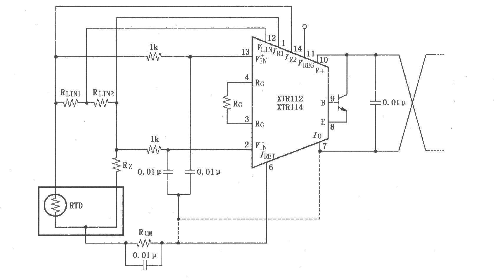
As shown in the figure, the long wire current loop transmission of this circuit will introduce radio frequency (RF) interference. RF energy will cause errors in the sensitive XT11l2/114 input, which will be manifested in the instability of the loop current or input line current. If the RTD sensor is at a long distance, interference will be introduced at the input of XTR112/114. If the transmitter and sensor are connected by short wires, the interference will come more from the connection wire of the current loop. The method to eliminate interference is to add a 0.01μF bypass capacitor filter at the input to reduce or eliminate interference. Connect the common point of these bypass capacitors to the IRET terminal. Although the DC voltage at the IRET terminal is not zero, it is the "ground" of the transmitter. In addition, connecting a 0.01μF capacitor between the V and Io terminals will help minimize output interference.
- 10Hz to 60MHz Frequency Meter/Counter Kit
- PIC Voltmeter
- 30W Digital RF Power Meter
- Music logic test pen
- Auxiliary circuit for measuring small resistance
- Using sub-milliohm resistors for current sensing has its advantages but also presents challenges
- Circuit for measuring 500VDV DC motor current composed of ISO102 and OPA27
- Level test circuit that indicates open (not tested) status by lighting up the decimal point dp
- Simple withstand voltage tester
- Wideband Strain Gauge Signal Conditioner with Boosted Excitation Voltage
- How the acceleration sensor works
- Low temperature temperature sensor
- SHD201 single feed water pump water level automatic control soft start circuit a
- Sensor lighting LED driver circuit
- Blocking sensor
- Linear transform position sensor (LVDT) position measurement circuit
- Basic connection diagram of bridge sensor and XTR104 02
- Basic connection diagram of potentiometer sensor and XTR104 03
- Sensor and AD7710/7712 signal conditioning ADC circuit
- Sensor analog signal input ADC701/SHC702 circuit


 京公网安备 11010802033920号