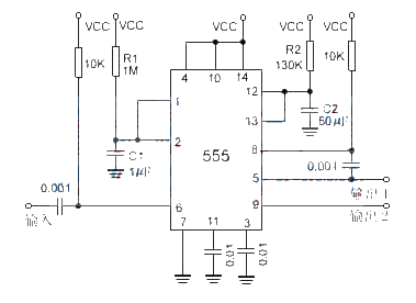
NE555 sequential timing circuit diagram
Source: InternetPublisher:通通 Keywords: NE555 timing circuit Updated: 2024/06/14
The first half of the 556 dual timer output is fed to the second half input via a 0.001μF coupling capacitor, giving a total delay equal to the sum of the individual delays. The first half of the timer is started by momentarily grounding pin 6. After the time interval determined by 1.1R1C1, the second timer begins delaying, with a value determined by 1.1R2C2.

- Photo exposure timer
- NE555 long time delay timing circuit
- Using NE555 to make a path detector
- 555 multifunctional refrigerator power socket circuit (1)
- 555 four-digit display capacitance meter circuit
- 555 rock lantern controller circuit
- 555 high power sweep siren circuit
- 555 chicken, dog, cat three sound and light toy circuit
- Selection of external circuit parameters for 555 monostable operating mode
- 555 calculator/stopwatch converter circuit
- Set timing circuit when power is on
- Low power timer circuit
- Darkroom exposure timer light circuit
- Light-controlled street light circuit using NE555 (1)
- Use NE555 to make light-controlled flashing warning lights
- Use NE555 to create touch and voice-controlled dual-function delay lights
- Clever use of NE555 as a cycle timer circuit with adjustable on-off time
- Pulse width modulation switching regulated power supply circuit diagram composed of NE555
- Circuit diagram of small boost switching regulated power supply composed of NE555
- Bipolar DC and DC voltage stabilizing converter circuit diagram composed of NE555


 京公网安备 11010802033920号