EEWORLDEEWORLDEEWORLD

Part Number

Search

10A02

Description
10 A, 50 V, SILICON, RECTIFIER DIODE
CategoryDiscrete semiconductor    diode   
File Size31KB,2 Pages
ManufacturerEIC [EIC discrete Semiconductors]
Environmental Compliance
Download Datasheet Parametric Compare View All

10A02 Online Shopping

Suppliers Part Number Price MOQ In stock  
10A02 - - View Buy Now

10A02 Overview

10 A, 50 V, SILICON, RECTIFIER DIODE

10A02 Parametric

Parameter NameAttribute value
Is it lead-free?Lead free
Is it Rohs certified?conform to
MakerEIC [EIC discrete Semiconductors]
Reach Compliance Codecompli
applicationGENERAL PURPOSE
Shell connectionISOLATED
ConfigurationSINGLE
Diode component materialsSILICON
Diode typeRECTIFIER DIODE
Maximum forward voltage (VF)1 V
JESD-30 codeO-PALF-W2
Maximum non-repetitive peak forward current400 A
Number of components1
Phase1
Number of terminals2
Maximum operating temperature150 °C
Minimum operating temperature-65 °C
Maximum output current10 A
Package body materialPLASTIC/EPOXY
Package shapeROUND
Package formLONG FORM
Peak Reflow Temperature (Celsius)NOT SPECIFIED
Maximum repetitive peak reverse voltage100 V
Maximum reverse current10 µA
surface mountNO
Terminal formWIRE
Terminal locationAXIAL
Maximum time at peak reflow temperatureNOT SPECIFIED
10A01-10A07
PRV : 50 - 1000 Volts
Io : 10 Amperes
FEATURES :
* Diffused Junction
* High current capability and Low Forward
Voltage Drop
* Surge Overload Rating to 600A Peak
* Low Reverse Leakage Current
* Pb / RoHS Free
SILICON RECTIFIER DIODES
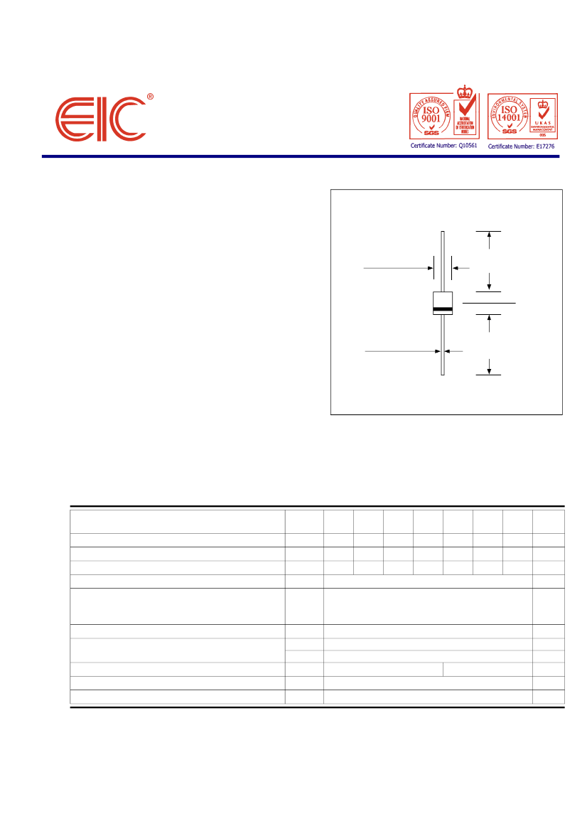
D6
1.00 (25.4)
MIN.
0.360 (9.1)
0.340 (8.6)
0.360 (9.1)
0.340 (8.6)
MECHANICAL DATA :
* Case : molded plastic
* Epoxy : UL94V-O rate flame retardant
* Lead : Axial lead solderable per MIL-STD-202,
Method 208 guaranteed
* Polarity : Color band denotes cathode end
* Mounting position : Any
* Weight : 2.049 grams
0.052 (1.32)
0.048 (1.22)
1.00 (25.4)
MIN.
Dimensions in inches and ( millimeters )
MAXIMUM RATINGS AND ELECTRICAL CHARACTERISTICS
Rating at 25
°
C ambient temperature unless otherwise specified.
Single phase, half wave, 60 Hz, resistive or inductive load.
For capacitive load, derate current by 20%.
RATING
Maximum Repetitive Peak Reverse Voltage
Maximum RMS Voltage
Maximum DC Blocking Voltage
Average Rectified Output Current (Note 1) Ta = 50°C
Non-Repetitive Peak Forward Surge Current 8.3 ms
Single half sine wave superimposed on rated load
(JEDEC Method)
Maximum Forward Voltage at I
F
= 10 Amps.
Maximum DC Reverse Current
at rated DC Blocking Voltage
Thermal Resistance
Operating and Storage Temperature Range
Notes
:
SYMBOL
10A01 10A02 10A03 10A04 10A05 10A06 10A07
UNIT
V
RRM
V
RMS
V
DC
I
O
I
FSM
V
F
I
R
I
R(H)
Cj
R
θJC
T
J
, T
STG
150
0.8
- 65 to + 150
50
35
50
100
70
100
200
140
200
400
280
400
10
600
1.3
10
100
80
600
420
600
800
560
800
1000
700
1000
V
V
V
A
A
V
µA
µA
pF
°C/W
°C
Ta = 25
°C
Ta = 100
°C
Typical Junction Capacitance (Note 2)
(1) Leads maintained at ambient temperature at a distance of 9.5 mm fro, the case.
(2) Measured at 1.0 MHz and applied reverse volage of 4.0V DC.
Page 1 of 2
Rev. 01 : October 27, 2005

10A02 Related Products

10A02 10A01 10A05 10A07 10A04 10A06
Description 10 A, 50 V, SILICON, RECTIFIER DIODE 10 A, 50 V, SILICON, RECTIFIER DIODE 10 A, 50 V, SILICON, RECTIFIER DIODE 10 A, 50 V, SILICON, RECTIFIER DIODE 10 A, 50 V, SILICON, RECTIFIER DIODE 10 A, 50 V, SILICON, RECTIFIER DIODE
Is it lead-free? Lead free Lead free - - Lead free Lead free
Is it Rohs certified? conform to conform to - - conform to conform to
Maker EIC [EIC discrete Semiconductors] EIC [EIC discrete Semiconductors] - - EIC [EIC discrete Semiconductors] EIC [EIC discrete Semiconductors]
Reach Compliance Code compli compli - - compli compli
application GENERAL PURPOSE GENERAL PURPOSE - - GENERAL PURPOSE GENERAL PURPOSE
Shell connection ISOLATED ISOLATED - - ISOLATED ISOLATED
Configuration SINGLE SINGLE - - SINGLE SINGLE
Diode component materials SILICON SILICON - - SILICON SILICON
Diode type RECTIFIER DIODE RECTIFIER DIODE - - RECTIFIER DIODE RECTIFIER DIODE
Maximum forward voltage (VF) 1 V 1 V - - 1 V 1 V
JESD-30 code O-PALF-W2 O-PALF-W2 - - O-PALF-W2 O-PALF-W2
Maximum non-repetitive peak forward current 400 A 400 A - - 400 A 400 A
Number of components 1 1 - - 1 1
Phase 1 1 - - 1 1
Number of terminals 2 2 - - 2 2
Maximum operating temperature 150 °C 150 °C - - 150 °C 150 °C
Minimum operating temperature -65 °C -65 °C - - -65 °C -65 °C
Maximum output current 10 A 10 A - - 10 A 10 A
Package body material PLASTIC/EPOXY PLASTIC/EPOXY - - PLASTIC/EPOXY PLASTIC/EPOXY
Package shape ROUND ROUND - - ROUND ROUND
Package form LONG FORM LONG FORM - - LONG FORM LONG FORM
Peak Reflow Temperature (Celsius) NOT SPECIFIED NOT SPECIFIED - - NOT SPECIFIED NOT SPECIFIED
Maximum repetitive peak reverse voltage 100 V 50 V - - 400 V 800 V
Maximum reverse current 10 µA 10 µA - - 10 µA 10 µA
surface mount NO NO - - NO NO
Terminal form WIRE WIRE - - WIRE WIRE
Terminal location AXIAL AXIAL - - AXIAL AXIAL
Maximum time at peak reflow temperature NOT SPECIFIED NOT SPECIFIED - - NOT SPECIFIED NOT SPECIFIED
Power in Watts expressed in dB
Power in Watts expressed in dB Power in Watts expressed in dBdB = 10 log (Pout/ Pin)where dB is the power expressed in DecibelPout is the output powerPin is the input power in reference to 1 wattPower...
JasonYoo RF/Wirelessly
Under CE, use the port to operate the GPS module, power consumption is related
In CE, use the Com port to operate GPS. If the GPS port is open, the GPS module is in operation and consumes more power. If the port is closed, the GPS module is in stop state and does not consume pow...
asdfgh123 Embedded System
[Raspberry Pi Pico Review] ADC Acquisition
[i=s]This post was last edited by 1nnocent on 2021-3-29 15:55[/i]I found one difference, that is, there is no reference voltage chip on the board. Therefore, the reference voltage of the board is the ...
1nnocent DIY/Open Source Hardware
Help, find a foreign literature
I am working on my graduation thesis, about the temperature fuzzy control system of high temperature and high pressure dyeing machine. Now I need to find a foreign literature to translate, but I can't...
高PING战士 Sensor
Reprint of the 09.05 version of the Common Component Selection Table
Well, it is reproduced, the copyright belongs to the original author....
aiwenzx Analog electronics
How to draw PCB package according to component size? Do you need to add 3D when drawing the package yourself?
For example:I draw a 1.2mm*2mm block diagram, and then draw 0.2*0.4 pins. Is it enough to place them according to the pin spacing? What other steps are needed? Why does the picture I drew look wrong?...
pengbiao1210 PCB Design

EEWorld
subscription
account

EEWorld
service
account

Automotive
development
circle

Robot
development
community

Index Files: 2065  2143  602  2262  1823  42  44  13  46  37 
Datasheet   0 1 2 3 4 5 6 7 8 9 A B C D E F G H I J K L M N O P Q R S T U V W X Y Z
Room 1530, 15th Floor, Building B, No. 18 Zhongguancun Street, Haidian District, Beijing Telephone: (010) 82350740 Postal Code: 100190
Copyright © 2005-2026 EEWORLD.com.cn, Inc. All rights reserved 京ICP证060456号 京ICP备10001474号-1 电信业务审批[2006]字第258号函 京公网安备 11010802033920号