

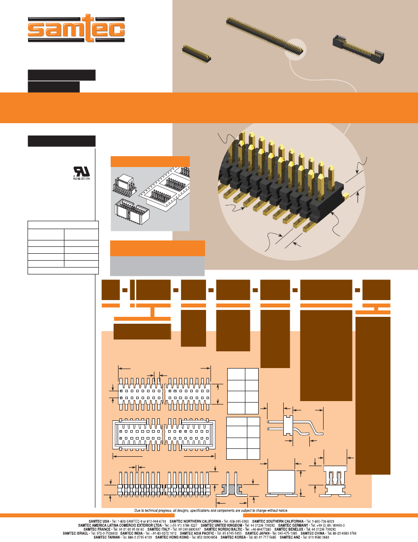
Board Connector, 136 Contact(s), 2 Row(s), Male, Straight, 0.032 inch Pitch, Surface Mount Terminal, Black Insulator, Receptacle
| Parameter Name | Attribute value |
| Is it lead-free? | Lead free |
| Is it Rohs certified? | conform to |
| Maker | SAMTEC |
| Reach Compliance Code | compliant |
| ECCN code | EAR99 |
| Other features | PLASTIC PICK&PLACE PAD |
| Body/casing type | RECEPTACLE |
| Connector type | BOARD CONNECTOR |
| Contact to complete cooperation | GOLD FLASH OVER NICKEL (50) |
| Contact completed and terminated | Gold (Au) - with Nickel (Ni) barrier |
| Contact point gender | MALE |
| Contact material | PHOSPHOR BRONZE |
| contact mode | RECTANGULAR |
| Contact style | SQ PIN-SKT |
| Insulator color | BLACK |
| insulator material | LIQUID CRYSTAL POLYMER (LCP) |
| JESD-609 code | e4 |
| Plug contact pitch | 0.032 inch |
| Match contact row spacing | 0.047 inch |
| Installation method | STRAIGHT |
| Installation type | BOARD |
| Number of connectors | ONE |
| PCB row number | 2 |
| Number of rows loaded | 2 |
| Maximum operating temperature | 125 °C |
| Minimum operating temperature | -55 °C |
| PCB contact pattern | RECTANGULAR |
| PCB contact row spacing | 3.302 mm |
| Plating thickness | 10u inch |
| Rated current (signal) | 2.7 A |
| Guideline | UL |
| reliability | COMMERCIAL |
| Terminal pitch | 0.7874 mm |
| Termination type | SURFACE MOUNT |
| Total number of contacts | 136 |
 京公网安备 11010802033920号


