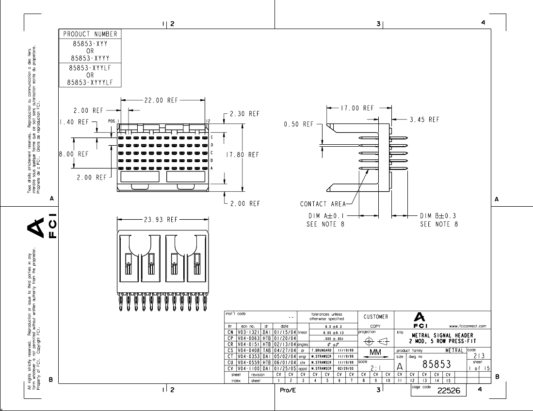
Board Connector, 60 Contact(s), 5 Row(s), Male, Straight, 0.079 inch Pitch, Press Fit Terminal, Locking, Plug,
| Parameter Name | Attribute value |
| Is it Rohs certified? | incompatible |
| Reach Compliance Code | compliant |
| Other features | POLARIZED |
| Board mount options | PEG |
| body width | 0.701 inch |
| subject depth | 0.669 inch |
| body length | 0.942 inch |
| Body/casing type | PLUG |
| Connector type | BOARD CONNECTOR |
| Contact to complete cooperation | TIN LEAD |
| Contact completed and terminated | Tin/Lead (Sn/Pb) |
| Contact point gender | MALE |
| Contact material | PHOSPHOR BRONZE |
| contact mode | RECTANGULAR |
| Contact resistance | 10 mΩ |
| Contact style | SQ PIN-SKT |
| DIN compliance | NO |
| Dielectric withstand voltage | 1400VAC V |
| Filter function | NO |
| IEC compliance | NO |
| maximum insertion force | .3614 N |
| Insulation resistance | 1000000000 Ω |
| insulator material | GLASS FILLED LIQUID CRYSTAL POLYMER |
| JESD-609 code | e0 |
| MIL compliance | NO |
| Manufacturer's serial number | 85853 |
| Plug contact pitch | 0.079 inch |
| Match contact row spacing | 0.079 inch |
| Mixed contacts | NO |
| Installation option 1 | LOCKING |
| Installation method | STRAIGHT |
| Installation type | BOARD |
| Number of connectors | ONE |
| PCB row number | 5 |
| Number of rows loaded | 5 |
| Maximum operating temperature | 125 °C |
| Minimum operating temperature | -55 °C |
| Options | GENERAL PURPOSE |
| PCB contact pattern | RECTANGULAR |
| PCB contact row spacing | 2.0066 mm |
| polarization key | POLARIZED HOUSING |
| Rated current (signal) | 1 A |
| Guideline | UL, CSA |
| reliability | COMMERCIAL |
| Terminal pitch | 2 mm |
| Termination type | PRESS FIT |
| Total number of contacts | 60 |
| UL Flammability Code | 94V-0 |
| Evacuation force-minimum value | .139 N |
 京公网安备 11010802033920号


