EEWORLDEEWORLDEEWORLD

Part Number

Search

K85X-ED-9S-K30

CategoryThe connector    The connector   
File Size901KB,1 Pages
ManufacturerKycon
Environmental Compliance
Download Datasheet Parametric View All

K85X-ED-9S-K30 Online Shopping

Suppliers Part Number Price MOQ In stock  
K85X-ED-9S-K30 - - View Buy Now

K85X-ED-9S-K30 Parametric

Parameter NameAttribute value
Is it lead-free?Lead free
Is it Rohs certified?conform to
MakerKycon
package instructionROHS COMPLIANT
Reach Compliance Codecompliant
ECCN codeEAR99
body width0.494 inch
subject depth0.213 inch
body length1.213 inch
Body/casing typeRECEPTACLE
Connector typeD SUBMINIATURE CONNECTOR
Contact to complete cooperationGOLD (30)
Contact completed and terminatedGold (Au)
Contact point genderFEMALE
Contact materialNOT SPECIFIED
contact modeSTAGGERED
Contact resistance13 mΩ
Contact styleRND PIN-SKT
DIN complianceNO
Dielectric withstand voltage700VAC V
empty shellNO
Filter functionNO
IEC complianceNO
Insulation resistance1000000000 Ω
Insulator colorBLACK
insulator materialGLASS FILLED POLYBUTYLENE TEREPHTHALATE
JESD-609 codee4
MIL complianceNO
Plug contact pitch0.109 inch
Match contact row spacing0.112 inch
Plug informationMULTIPLE MATING PARTS AVAILABLE
Mixed contactsNO
Installation option 1#4-40
Installation option 2THREADED
Installation methodSTRAIGHT
Installation typeBOARD
PCB row number2
Number of rows loaded2
Maximum operating temperature105 °C
Minimum operating temperature-55 °C
OptionsGENERAL PURPOSE
PCB contact patternSTAGGERED
PCB contact row spacing2.8448 mm
Plating thickness30u inch
Rated current (signal)2 A
GuidelineUL
reliabilityCOMMERCIAL
Shell surfaceTIN
Shell materialSTEEL
Housing size1/E
Terminal length0.185 inch
Terminal pitch1.397 mm
Termination typeSOLDER
Total number of contacts9
2D Drawing
Solder Profile
Certificate of Origin
IGES
CofC RoHS Compliant
Check Stock
STEP
CofC REACH Compliant
Request a Sample
3D PDF
UL Plastic File
Send Us An Email
Generated Part Number
K85X-EA-9P
Part Number Builder
LR78160
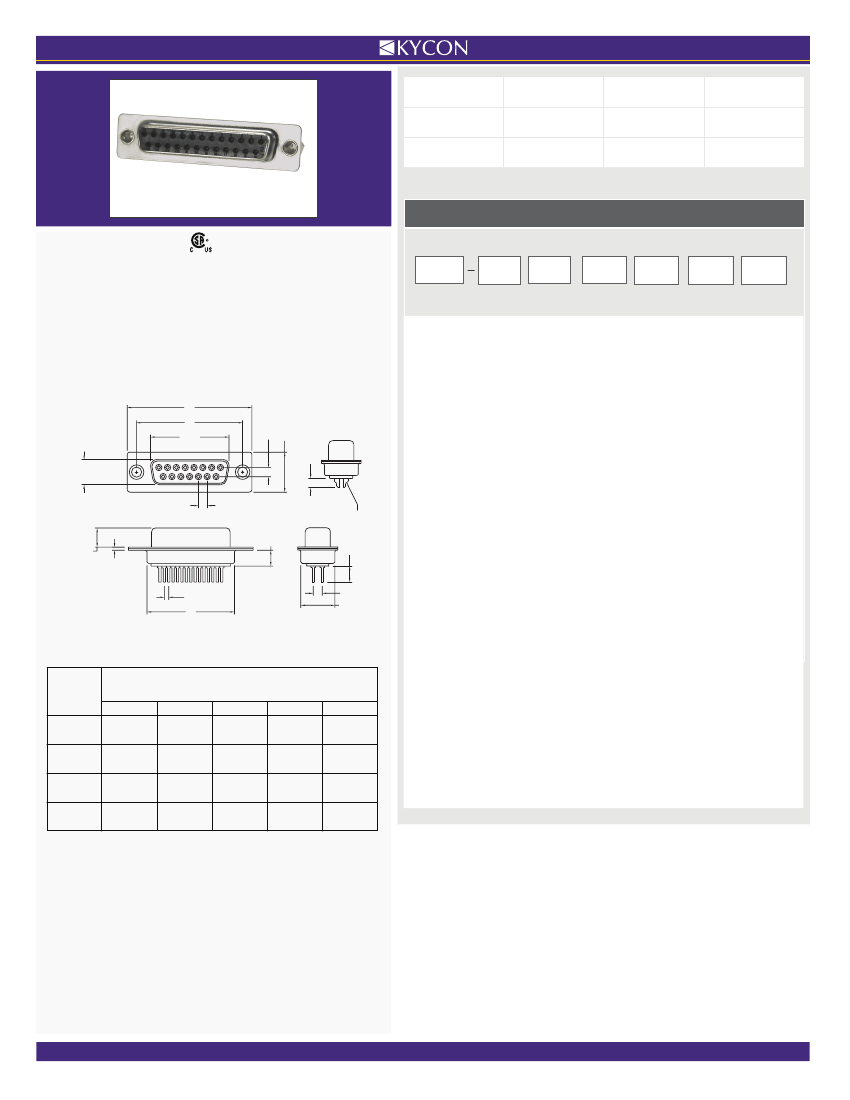
D-SUBMINIATURE CONNECTORS:
K85X
Series
Vertical PCB Mount and Solder Cup
K85X Series
Dimensions
Dimensions in mm
K85X
Series
E
Shell
Type
A
Pin
Type
9
Contact
Option
P
Contact
Type
Mounting
Option
Plating
Option
Series
K85X
-
D-Subminiature
Vertical
Connector
Contact Shell Size
E
- 9 Contacts
A
- 15 Contacts
B
- 25 Contacts
C
- 37 Contacts
3.5
C
A, A1
12.55
2.84
B
8.36 Plug Interior,
7.90 Socket Exterior
2.77
Solder Cups
6.1 Plug,
5.8 Socket
0.90
4.50
Contact Construction, Pin Type
A
- Precision Formed, Solder Cup (Not Available with BR/BRJ)
D
- Precision Formed, Vertical Pin (PCB Mount)
Contact Type
P
- Pin Contact (Plug)
S
- Socket Contact (Receptacle)
Mounting Option
Blank
- Through Hole
BR
- With #4-40 Threaded Boardlocks
BRJ
- #4-40 Threaded Boardlocks and
#4-40 Jackscrews Installed
K
- #4-40 Threaded Bushings
KJ
- #4-40 Threaded Bushings and #4-40 Jackscrews Installed
R
- Round Jackscrews
Plating Option
Blank
- Gold Flash
30
- 30µ” Gold
Contact Kycon for Other Options
1.385
D
2.84
10.72
Number
of Contacts
(Shell Size)
9 (E)
15 (A)
25 (B)
37 (C)
Dimensions (Inch/
mm)
A
.643
16.33
.971
24.66
1.511
38.38
2.159
54.84
A1
.666
16.92
.994
25.25
1.534
38.96
2.182
55.42
B
.984
24.99
1.312
33.32
1.852
47.04
2.500
63.50
C
1.213
30.81
1.541
39.14
2.088
53.04
2.729
69.32
D
.755
19.18
1.083
27.51
1.614
41.00
2.272
57.30
A = Exterior of Female Shell (S)
A1 = Interior of Male Shell (P)
Phone: +1.408.494.0330
l
Fax: +1.408.494.0325
l
WWW.KYCON.COM
l
2013
4.7
Voltage pulses cause LED lights to flicker
I have a PID-regulated heating rod in my circuit. Whenever the regulated temperature is reached, there will be a drastic voltage change in the circuit because a MOS tube is used as a switch. Later I f...
飞一个去 Analog electronics
Regarding the issue of creating a new project in vs2005, why is there no wince6 option?
1. I am using the micro2440 of Friendly Arm, and the software environment is vs2005+wince6. 2. I installed 2005 and patches first, and then installed wince6+patches SP1, SP2, SP3; there were no proble...
zl0801 Embedded System
[TI C2000 usage experience] CMD file interpretation & moving RAM functions from flash
First, the storage location of each data segment and the running location are stored and controlled in the cmd file. For example, the following segment: [code] .cinit : LOAD = FLASHC, PAGE = 0 /* Load...
a828378 Microcontroller MCU
Schematics of several LPC1700 development boards
Find some information for "Smart Home System":...
zhaojun_xf NXP MCU
Help with LCD driver chip parameters
When I was cleaning, I found a dedicated LCD, the driver is OKI M5299B, it's a pity to throw it away, but I want to use it but I don't have the information. Please help me, thank you. My email: [email...
quanzx Embedded System
Design Tips for Efficient Non-Inverting Buck-Boost Converters
[i=s]This post was last edited by dontium on 2015-1-23 11:27[/i]Buck-boost converters are widely used in industrial personal computers (IPC), point-of-sale (POS) systems, and automotive start-stop sys...
qwqwqw2088 Analogue and Mixed Signal

Technical ResourceMore

EEWorld
subscription
account

EEWorld
service
account

Automotive
development
circle

Robot
development
community

Index Files: 166  3  2769  1761  484  4  1  56  36  10 
Datasheet   0 1 2 3 4 5 6 7 8 9 A B C D E F G H I J K L M N O P Q R S T U V W X Y Z
Room 1530, 15th Floor, Building B, No. 18 Zhongguancun Street, Haidian District, Beijing Telephone: (010) 82350740 Postal Code: 100190
Copyright © 2005-2026 EEWORLD.com.cn, Inc. All rights reserved 京ICP证060456号 京ICP备10001474号-1 电信业务审批[2006]字第258号函 京公网安备 11010802033920号