This project
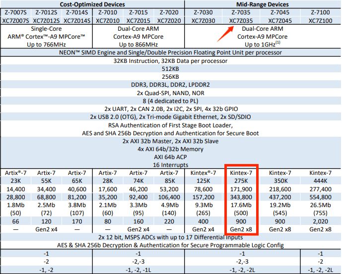
aims to open-source the ZYNQ7035 core board and an 8-bit 1GSPS 4-channel ADC module. The previous project, featuring a 7020 core board and RF module, was geared towards general applications and electronics design competitions; this 7035 core board and high-speed ADC are geared towards high-speed communication and high-speed electronic measurements such as a 1GSPS 4-channel oscilloscope. The ZYNQ7035PS side uses a dual-core Cortex-A9, while the PL side is based on the Kintex-7 architecture, which is superior to the Artix-7 architecture of the 7020 and
7010, offering stronger timing control capabilities. The PL side has 275k logic cells, more than three times that of the 7020 and nearly ten times that of the 7010. The DSP resources are more than four times that of the 7020, allowing for steeper filter designs and the deployment of larger-scale DSP algorithms. Simultaneously, the BRAM resources are more than three times larger than the 7020, enabling the ILA to capture more data and facilitating debugging.
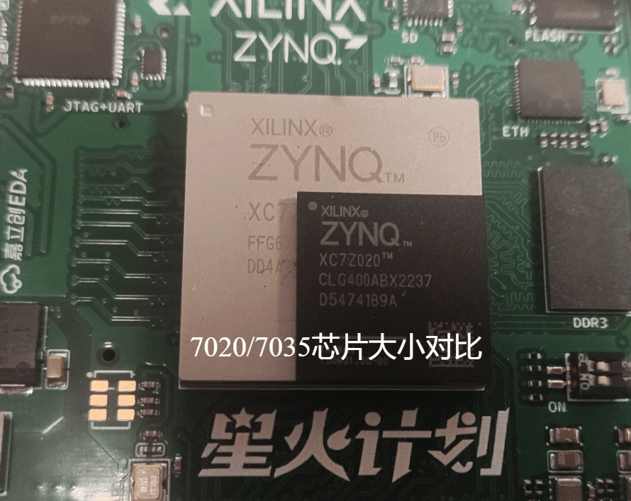
Compared to the ZYNQ7035 which costs 3000-4000 yuan on TB, the core board BOM cost of this open source is only a few hundred yuan, which provides strong help to electronic enthusiasts who need ZYNQ7035. Moreover, this project is the first open source 7035 on the oshwhub platform, and it seems to be the first one on the entire network!

Of course, in addition to the ZYNQ7035 core board, this project will also open source the HMCAD1511 8bit 4-channel 1G sampling rate high-speed ADC module and driver.

The open source agreement
is prohibited for commercial use without the author's permission. Reprints or citations must indicate the original author and project link.
Project related functional
resources introduction:
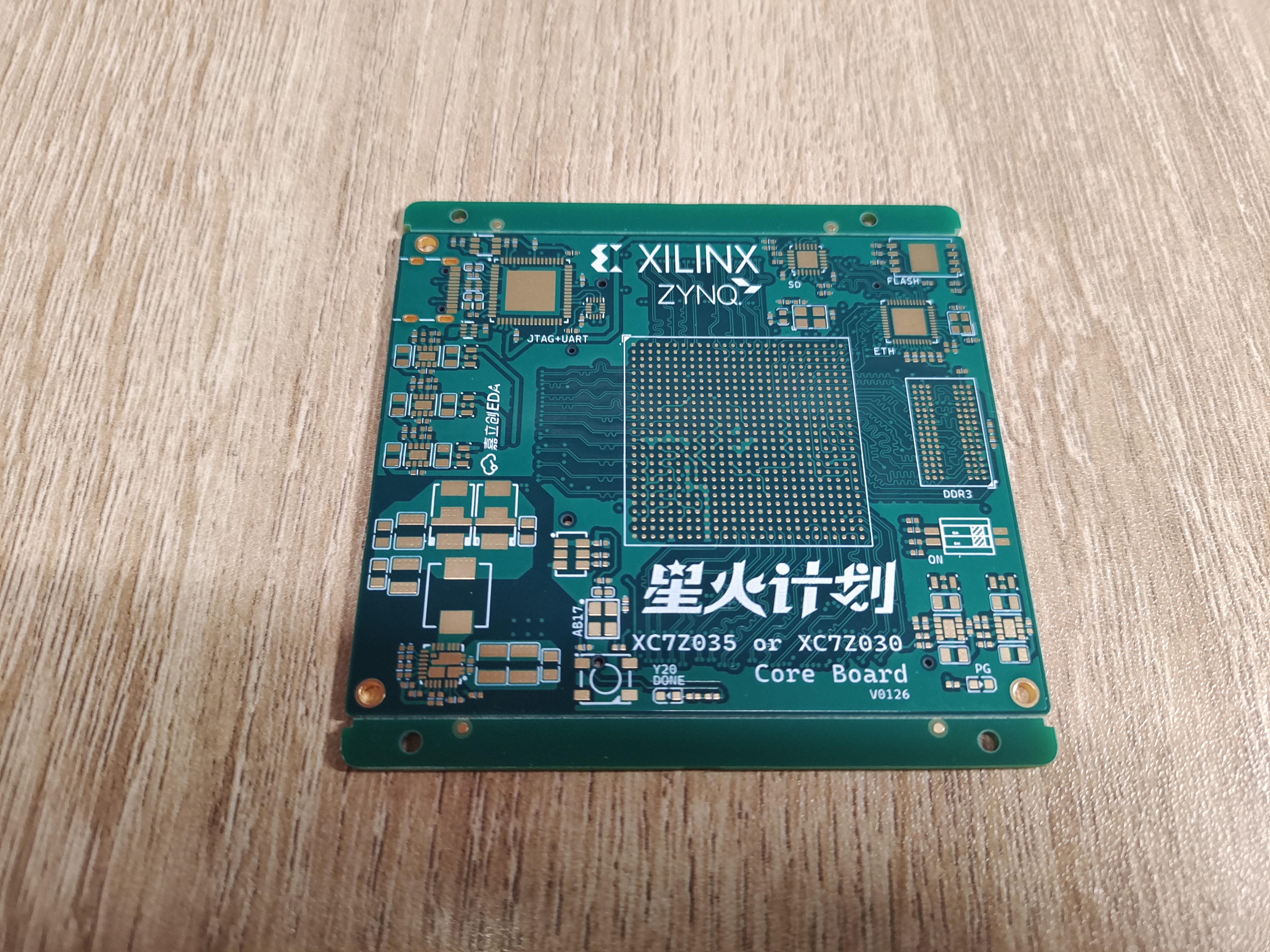
(1) ZYNQ7035 core board PS end: Onboard 1 DDR3, QSPI FLASH, SD card adapter chip, Gigabit Ethernet, JTAG, UART.
(2) TYPEC Port Description (Important!!): Using the FT2232 chip, single-chip JTAG+UART operation is completed. The USB port uses TYPEC, which includes ESD+common-mode filtering and an ideal diode to prevent reverse current flow. No more debugging, power supply, programming, and connecting a bunch of wires (even various old USB interfaces...). One TYPEC is enough! A boon for developers~
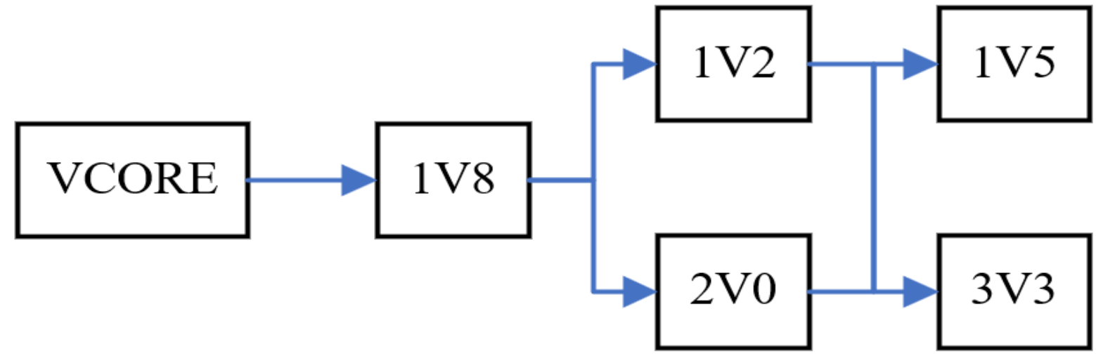
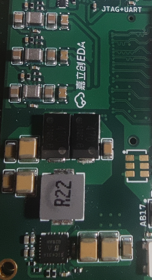
(3) Power Management: The core power supply used in this project is Vishay's SIC431, which features remote sampling, high efficiency (97% peak efficiency), and 24A power supply capability. Furthermore, this device is internally compensated and does not require an external ESR network to achieve loop stability. The auxiliary power supply is TPS82130, our old friend :) The power-on sequence is shown in the figure
(4) ZYNQ7035 core board PL end: The PL end leads out a group of GTX BANK; 36 pairs of differential equal length High Performance BANK with a level of 1.8V; 35 pairs of differential equal length High Range BANK with a level of 3.3V, a total of 158 IOs. Due to the limitation of the 6-layer board, no more IOs are led out, but it is enough for use.
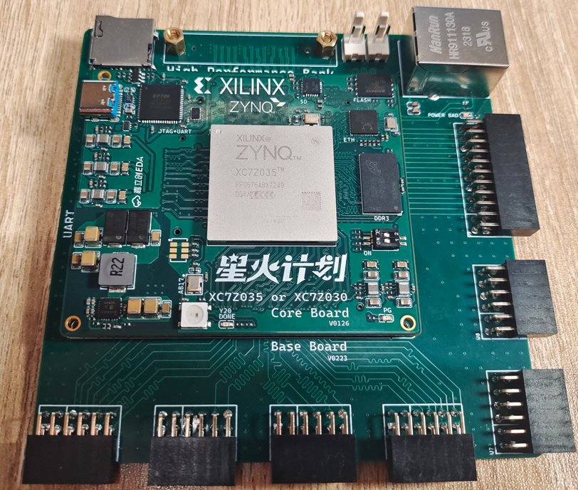
(5) ZYNQ7035 baseboard: This time, a matching baseboard was open sourced, in which HRbank is led out as PMOD interface (PMOD is good civilization!), HPbank is led out as BTB connector. The PS end is given an Ethernet interface, two 2510 power supply ports, an SD card interface, an LDO to power PMOD, and a power protection IC: with fast overvoltage clamping, adjustable overvoltage lockout, adjustable current limit, adjustable output slew rate control and overheat protection. Since there is no equipment for testing GTX at the moment, the baseboard does not have GTX pins. You can draw it yourself if needed.
(6) HMCAD1511: 8-bit 1GSPS ADC, analog front-end is LMH6521 high-performance dual-channel DVGA, -3dB bandwidth is 1.2GHz. Input impedance is 50Ω, programmable gain, dynamic range is 31.5dB, step size is 0.5dB. Onboard phase-locked loop HMC832 provides sampling clock. The interface uses 1.8V LVDS. Onboard power management uses integrated DCDC and ultra-low noise ultra-high PSR LLDO, and uses feedthrough capacitor filtering. The input is 5V 2510 interface.
Project attributes
This project is being published for the first time and is my original project. The project has not won any awards in other competitions.
Project Progress
(I) ZYNQ7035 Core Board:
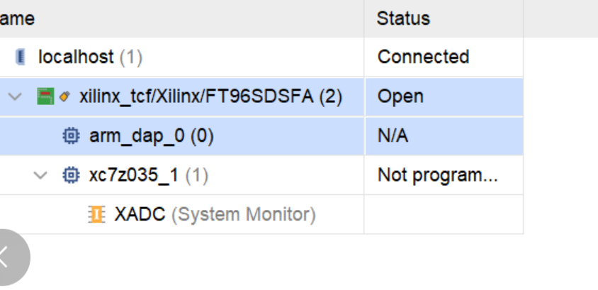
(1) ZYNQ Chip: Normal operation, VIVADO normal connection:
(2) DDR3: Normal operation, 0 errors:

(3) JTAG+UART: FT2232 normal operation, JTAG and UART can be used normally.
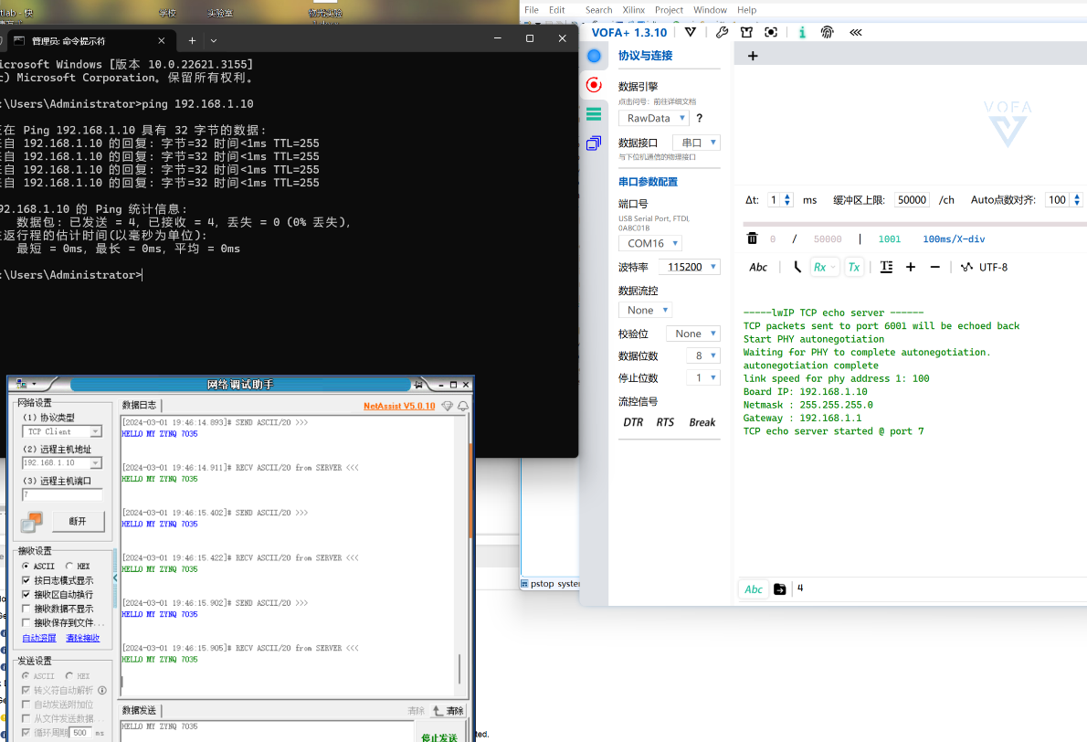
(4) Ethernet: RTL8211 normal operation, network loopback test results:
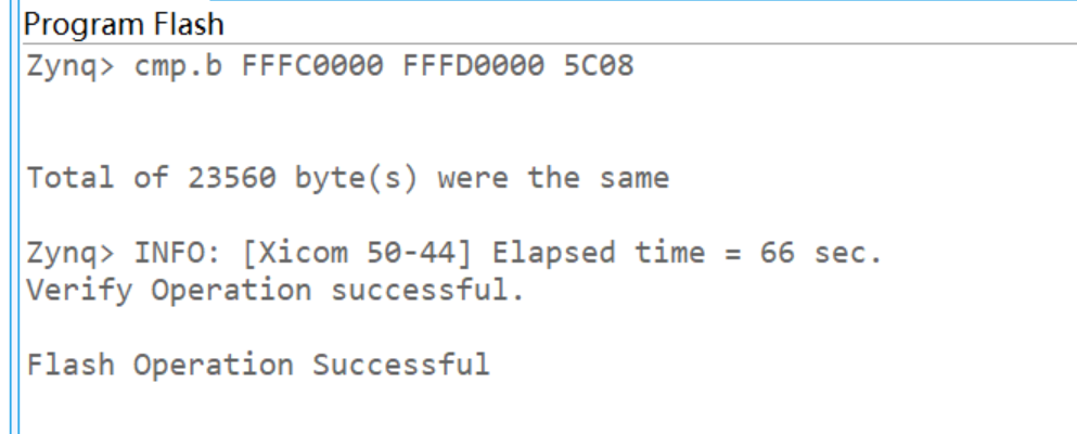
(5) Firmware and Startup: QSPI FLASH firmware results, offline startup results:
(II) HMCAD1511:
Normal operation, Figure 1 shows the data test mode, and it can be seen that all channels are working normally. Figure 2 shows the ILA data acquisition data imported into MATLAB for processing, and the FFT and time domain waveforms are shown in the figure.


Design Description
I. ZYNQ7035 Core Board:
(1) Power Supply Section: The core power supply uses Vishay's SIC431, with a maximum output current of 24A; the auxiliary power supply uses a TPS82130 integrated inductor DCDC converter, which can output a maximum current of 3A, with a total of 6 voltages. The power-on sequence is 1V0->1V8->1V2&2V0->1V5&3V3. For detailed parameters and requirements, please refer to the Xilinx official manual.
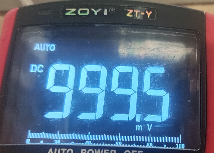
The core power supply test result is 999.5mV with an error of 0.5 per thousand. The ripple is 8mV peak-to-peak and 500uV effective value, which meets the Xilinx official requirements.
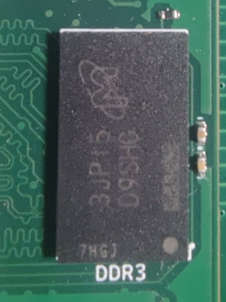
(2) DDR3: DDR3 uses Micron's single-chip MT41K256M16 4Gbit.
(3) FLASH: QSPI FLASH uses W25Q256JVEIQ (or W25Q128JVEIQ)

(4) SD card adapter: SD card adapter uses TI's TXS02612RTWR
(5) Ethernet: Ethernet uses REALTEK's RTL8211

(6) Clock: PS uses a 33.3333MHZ 20ppm active crystal oscillator, PL uses a 100Mhz 20ppm active crystal oscillator. GTX uses a 125MHZ differential crystal oscillator (LVDS)
(7) JTAG+UART: Uses FT2232HQ, a single chip completes two tasks.
(8) Board-to-board connector IO resources: A set of GTX BANK is brought out from the PL end; 36 pairs of differential equal-length High Performance BANK with a level of 1.8V; 35 pairs of differential equal-length High Range BANK with a level of 3.3V, for a total of 158 IOs. PS leads to ETH, SD card, JTAG, and other pins can be implemented using PL pin resources through EMIO if needed.
(9) Boot mode selection: Three boot modes are provided, namely JTAG boot, QSPI FLASH boot, and SD card boot. Changes can be made through the DIP switches on the core board:
Boot mode
Switch 1
Switch 2
JTAG Start
ON QSPI FLASH Start ON
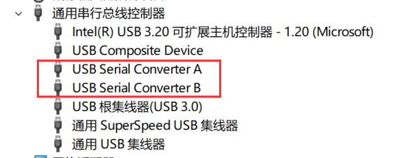
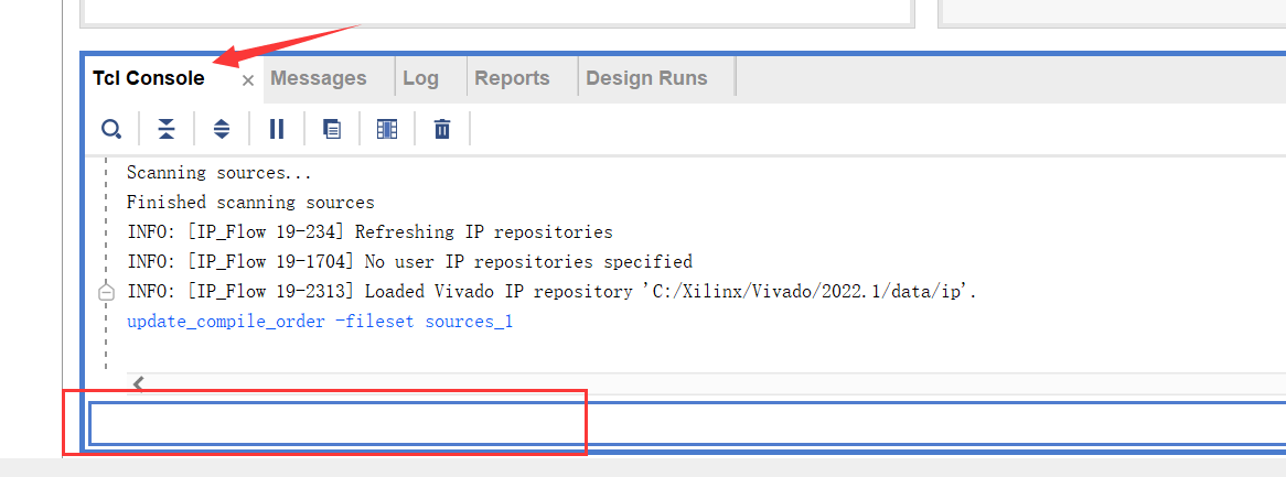
OFF SD Card Start OFF OFF ( 10) ZYNQ chip model: XC7Z035-FFG676, XC7Z035-2FFG676, XC7Z030-2FFG676, XC7Z030-FFG676 Software description (1) ZYNQ7035 provides UART, RGBLED, DRAM, Ethernet test projects (see attachment), VIVADO version is 2022.1 (2) HMCAD1511 driver project is zynq Ultrasale +MPSOC XCZU3EG (interface definition compatible with ZYNQ7035 baseboard, porting required) see attachment, VIVADO version 2022.1. Physical demonstration design notes: (I) When soldering the Zynq core board, it is recommended to solder the power supply first, test the power supply voltage and startup sequence to ensure they are normal, and then solder the feedthrough capacitors and other chips to prevent chip damage due to abnormal power supply. (II) When soldering the ZYNQ7035 chip with the steel cover, it is recommended to use a BGA soldering station, not a hot air gun, or choose JLCPCB SMT to directly mount it. (III) Suggested soldering order: power supply - BGA chip - front peripheral circuit - back capacitors and resistors - connectors. (IV) After soldering, you can verify by burning the RGBLED test program in the attachment. (V) FT2232HQ program burning: Note that changing FT2232 to JTAG+UART requires program support and cannot be used without burning. For Vivado 2022, it comes with built-in support for FT2232. The program can be burned by following these steps: (1) Open Vivado (any project) and connect the core board to the Type-C port (plug in the cable). (2) Open Device Manager to check if there is a new USB device inserted. If not, it means there is a hardware problem. Normally, as shown in the figure, it indicates that there is a USB Serial A and B connection. (3) Open Vivado's TCL, enter program_ftdi -write -ftdi FT2232H -serial 0ABC01 -vendor "my vendor co" -board "my board" -desc "my product desc" and press Enter to send. After a while, it will display INFO: FTDI Programming Passed and the program burning is complete. At this time, configure FT2232 port A as JTAG and port B as UART. Then you can happily use ZYNQ7035~ (VI) For the protection of the USB port, the ideal diode for anti-reverse current is selected at 2.5A. At this time, the power of the whole board is limited to 12.5W. If higher power is needed, it can be powered through the base plate. Generally speaking, 10W is more than enough for ZYNQ7035. (VII) The core board of ZYNQ7035 is a 6-layer board with a through-hole process by JLCPCB, 3133 stacked, and the impedance can be selected as ±20%. HMCAD1511 is a 4-layer board with 7628 stacked. Project attachment instructions: (1) Due to the 50M upload limit, the test program will be posted on Baidu Netdisk: ZYNQ7035 Test Program Extraction code: SDMY (2) Detailed demonstration and instruction videos will be posted on Bilibili. The link is in the pinned comment section. The project attachment is the ZYNQ7035 FLASH startup video.


 京公网安备 11010802033920号

 CCL100DNY1-V


