1. Video Link:
Bilibili Video -- Function Demonstration
2. Project Overview
This project is a writing robot based on ESP32, capable of creating text, diagrams, and hand-drawn illustrations on various paper media. Through a user-friendly web front-end interface, users can preview and control the robot in real-time on multiple devices (such as PCs, mobile phones, and tablets).
Project Actual Images:
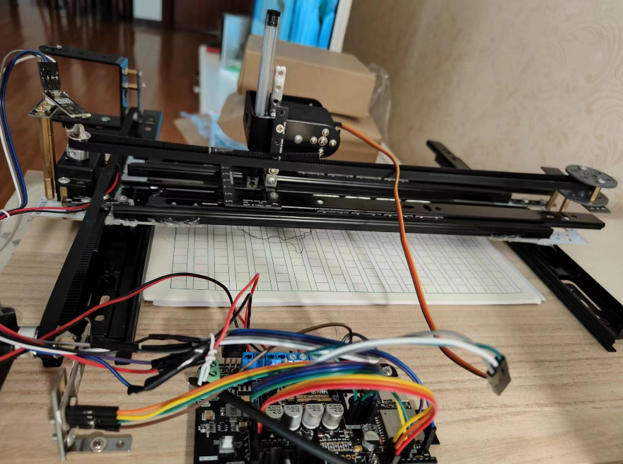
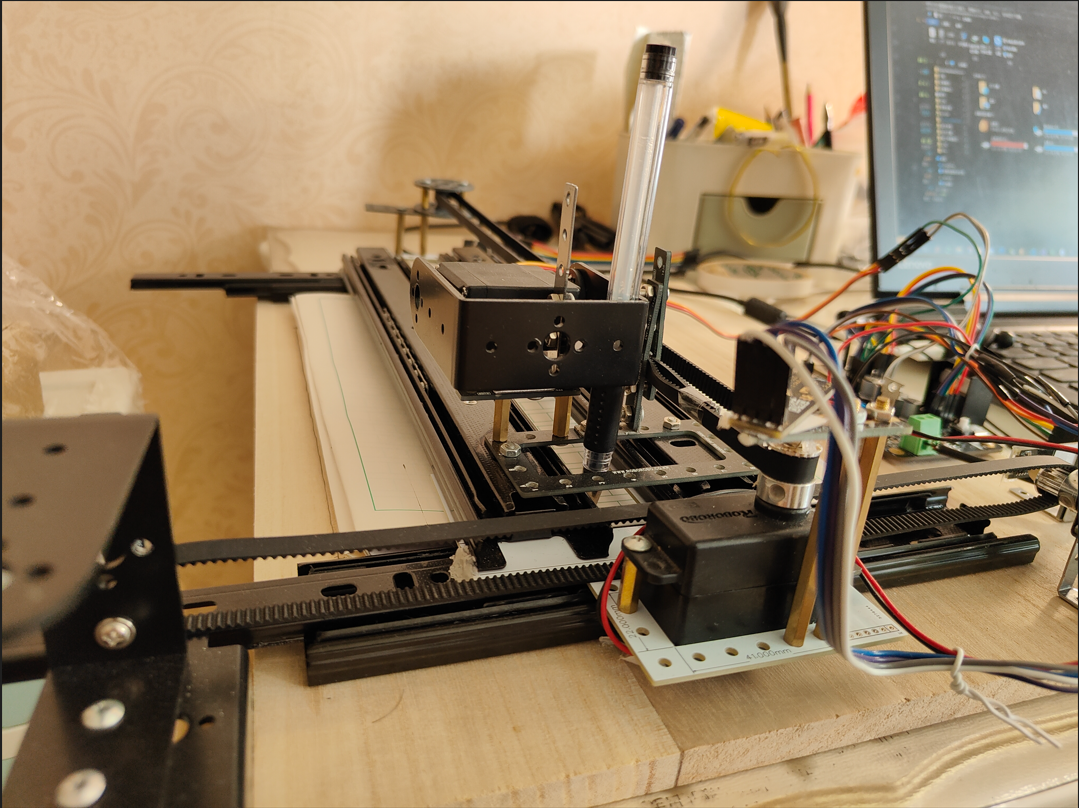
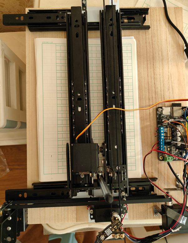
Control Interface:

2.1 Innovation Points: Ultra-Low Cost
Compared to traditional writing robots, this project adopts a unique innovative solution found nowhere else online. Its innovation is mainly reflected in the following aspects:
Cost Optimization: Abandoning traditional servo and stepper systems, it boldly adopts more economical DC motors, significantly reducing overall costs. A PID algorithm + magnetic encoder is used to compensate for the accuracy deficiencies of traditional DC motors.
Mechanical Design: Inexpensive drawer rails (costing only 2 yuan each, while professional rails often cost hundreds) are used instead of expensive professional rails, further reducing costs while ensuring the robot's stability and reliability as much as possible.
2.2 Project Functions
This design integrates two ordinary DC motors and one dedicated motor for lifting and lowering the pen. Utilizing Bluetooth Low Energy (BLE) communication technology, efficient text, chart, and hand-drawn creation is achieved. Furthermore, a user-friendly web interface makes real-time preview and command control simple and intuitive.
2.3 Project Parameters
: Motor Control: An MT6701 magnetic encoder is used for non-contact measurement, combined with a PID closed-loop control algorithm to achieve precise movement of the X and Y axis motors, ensuring high accuracy during writing.
Pen Control Mechanism: An MG995 servo motor controls the pen's lifting and lowering actions.
Motor Drive: An L298N full-bridge driver chip drives two ordinary DC motors, responsible for X and Y axis movement respectively.
Power Management: A Belling DC-DC step-down solution is used, paired with a 3.3V ultra-low dropout LDO, to effectively separate the 12V, 5V, and 3.3V power domains.
Main Control Chip: An ESP32 is used, with a built-in Bluetooth module, supporting two physical button operations.
Power Monitoring: Intelligent power management is achieved based on an ADC.
Development Environment: ESP-IDF v5 is used, and all code is written in C++11, strictly adhering to object-oriented programming standards. The official C language API is object-orientedly encapsulated, making it easy to maintain and extend, reducing the cognitive burden on developers.
Bluetooth Library: Nimble is used to implement Bluetooth communication between the host computer and the slave computer.
Front-end Technology Stack: A modern and engineered front-end technology stack is adopted, using Vue + Ant Design + TypeScript + Vite to build a modern web front-end interface, providing cross-platform support and an excellent user experience.
3. Detailed Principle Analysis (Hardware Part)
This project consists of the following parts: power supply, motor drive, main control, magnetic encoder, and mechanical guide rail.
The PCB layout of the entire board is as follows:

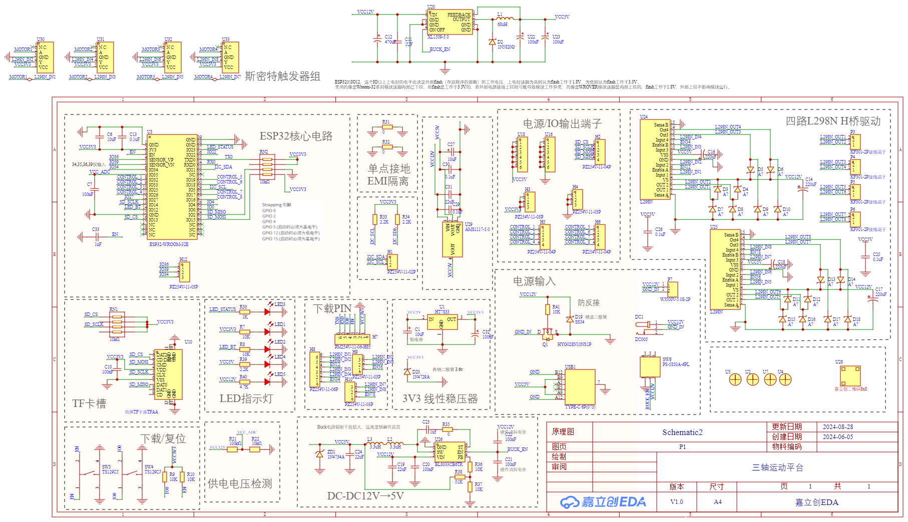
The schematic diagram of the entire board is as follows:


3.1 Power Supply
The PCB layout of the power supply part is as follows. Note that the SW wires of the DCDC circuit should be as thick and short as possible, and the feedback should be grounded to reduce ripple.


This power supply circuit is explained step-by-step according to the power current flow:
Power Input
: Power is input from "DC01" and "DC05" in the "Power Input" section, and then connected to "VCC12V" and "GND_IN" via "DC01" and "DC05".
Reverse Connection Protection: After the power input, an N-MOS transistor is used for reverse connection protection to ensure that the positive and negative terminals of the power supply are correctly connected.
DC-DC 12V→5V
DC-DC Converter: The 12V power supply is converted to 5V using Belling's DCDC solution (BL8033CB6TR).
Zener Diodes: Two Zener diodes, "ZD1" (1N4734A) and "1N4729A", are used to regulate the 5V and 3.3V outputs, ensuring the safety of the downstream load.
Power Switch: "SW6" (FS-5850A-6PL) controls the start and stop of the DCDC module.
3V3 Linear Regulator
: After the power supply is stepped down by a buck circuit, it is linearly regulated to 3.3V by "U1" (HT7833).
Regulating and Filtering Capacitors: The regulated 3.3V power supply is filtered and regulated by tantalum capacitor "C1" and electrolytic capacitor "C32" to ensure output voltage stability and improve the dynamic response performance of the power module.
Power Supply
Voltage Detection: The 5V power supply is divided by "R21" and "R22" to reduce the power supply voltage to 1/10, and then connected to the ADC input of the ESP32 via a filtering capacitor for power supply voltage detection.
USB Interface
: The circuit has a TYPE-C-6P interface "USB1" for 5V power supply in special conditions; data transmission is not allowed.
3.2 Motor Drive Section :
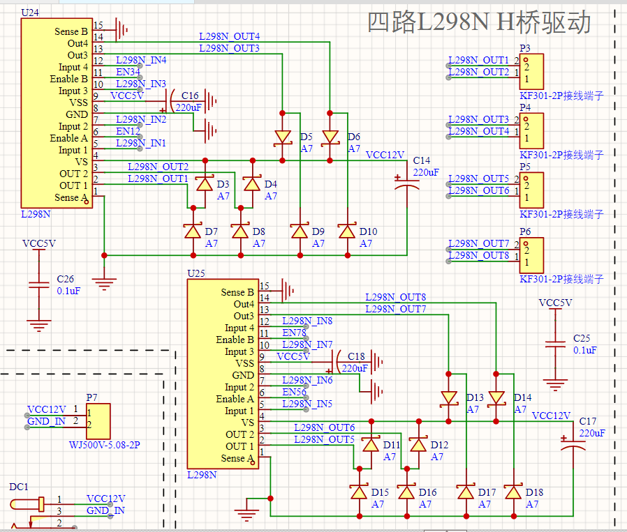
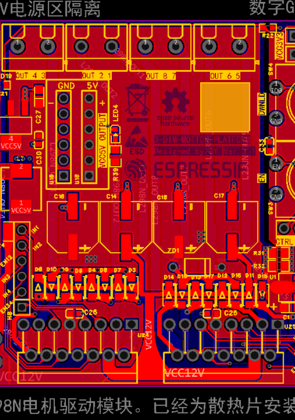
The L298N full-bridge driver chip is used to drive two ordinary DC motors, responsible for the X-axis and Y-axis movements respectively.
This is a design diagram of a four-channel L298N H-bridge driver circuit. The following are the main components and design specifications of the circuit. The circuit uses two L298N chips (U24 and U25), each capable of driving two motors. The pin functions of the L298N chips are as follows:
IN1-IN4: Input signals, used to control the forward and reverse rotation of the motors.
OUT1-OUT4: Output signals, connected to the two ends of the motor.
EN1/EN2: Enable signals, input PWM wave.
VS: Power supply voltage input, 5V.
VCC: Motor power supply voltage input, 12V.
GND: Ground.
VCC5V: 5V power supply, used for the logic section of the L298N chip.
VCC12V: 12V power supply, used for the motor drive section.
C16, C18, C17: Capacitors, used for filtering and stabilizing the power supply voltage.
Each motor output terminal (OUT1-OUT8) is connected to a diode (D3-D18). These diodes protect the L298N chip from the back EMF of the motor. When the motor suddenly stops or reverses, a back EMF is generated, and these diodes absorb this energy, protecting the chip.
Multiple terminals (P3-P6, P7) are used in the circuit to connect the external power supply and the motor. Each terminal has two pins, connected to the L298N chip's output and ground respectively.
C26, C25: 0.1uF capacitors, used for filtering and stabilizing the 5V power supply.
C14, C18, C17: 220uF capacitors, used for filtering and stabilizing the 12V power supply.
3.3 Main Control Section


ESP32 Core Circuit:
The ESP32 chip (ESP32-WROOM-32E) is the core of the circuit, providing various interfaces and functions.
The power supply section includes VCC3V3 and VCC_ADC, filtered by capacitors C6, C13, and C7.
Control signals (such as EN, SD_CS, SD_SCLK, SD_MISO, SD_MOSI, etc.) are connected to the corresponding pins of the ESP32.
Single-point grounding EMI isolation:
EMI isolation between analog and digital circuits is achieved through resistors R31 and R32.
TF Card Slot:
The TF card slot is connected to the ESP32 via signal lines such as SD_CS, SD_SCLK, SD_MISO, and SD_MOSI for data transmission.
LED Indicator:
The LEDs are controlled by resistors R30, R7, R8, R39, and R40 to indicate the circuit's operating status.
Download/Reset:
Download and reset operations are performed via switches SW3 and SW4 to ensure normal circuit startup and debugging.
Download PIN:
Connected to the GPIO pin of the ESP32 via a resistor and capacitor network for downloading and debugging.
3.4 Magnetic Encoder Section
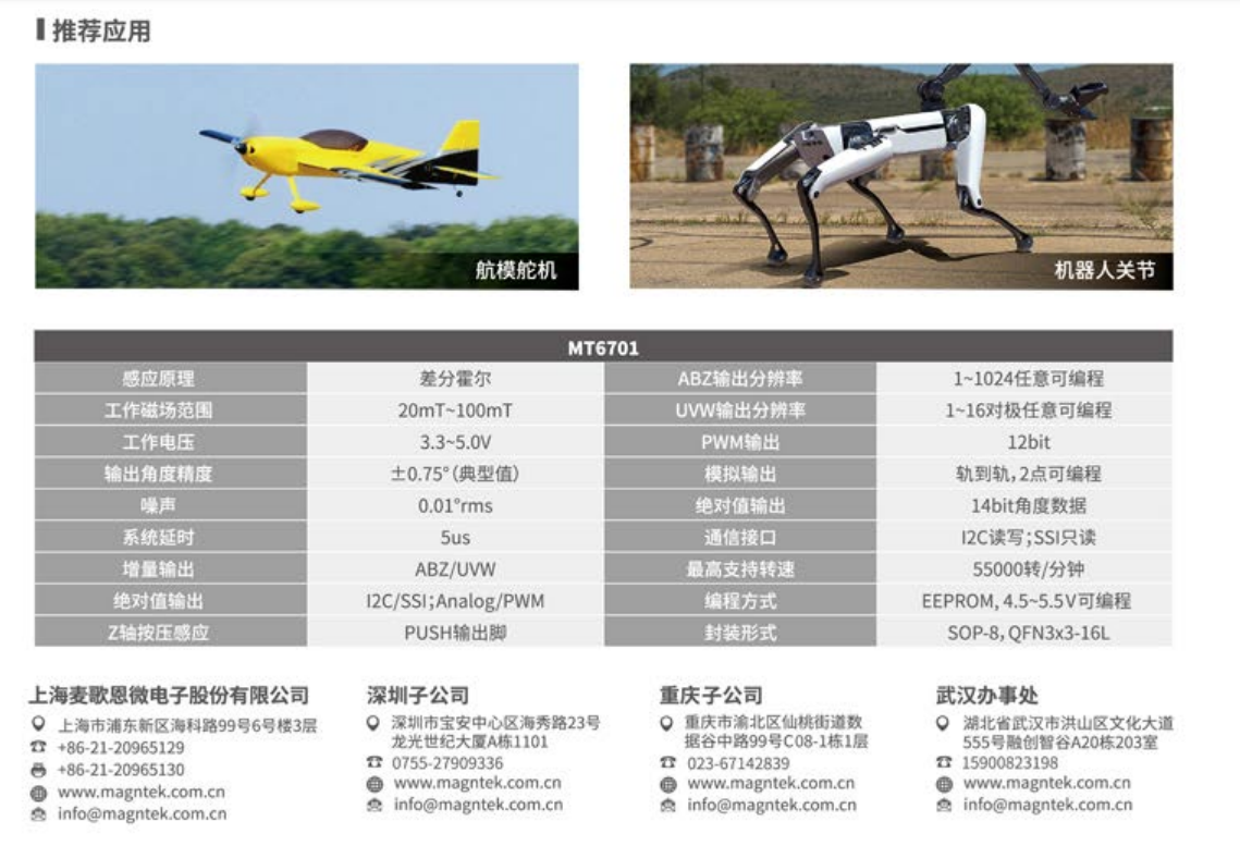
3.4.1 Introduction to the MT6701 Magnetic Encoder
The MT6701 magnetic encoder is a non-contact position sensor that determines rotational angle or linear position by detecting changes in the magnetic field. This type of encoder features high resolution, long lifespan, and strong anti-interference capabilities, making it ideal for applications requiring high-precision positioning.
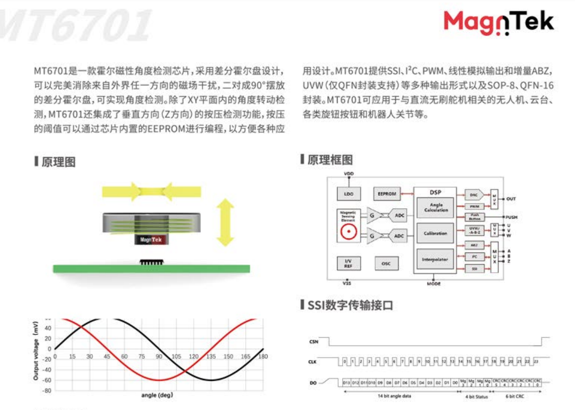
3.4.2 Working Principle
Magnetic Field Detection:
The MT6701 internally contains a set of magnetic sensing elements (Hall effect sensors) arranged in a circular path to detect changes in the magnetic field generated by a magnet.
When the magnet rotates relative to the encoder, the magnetic sensing elements detect changes in magnetic field strength and convert these changes into electrical signals.
Signal Processing:
The output electrical signals are processed by internal circuitry and converted into digital signals.
These digital signals represent the angular position of the magnet relative to the encoder.
Interface Output:
The MT6701 provides SPI and I2C interfaces for communication with the microcontroller.
By reading I2C data, the main control chip (ESP32) can obtain precise angular position information.
3.4.3 Hardware Implementation

Connection Method:
The MT6701 follows the standard I2C interface and has four pins: VCC, GND, SCL, and SDA.
These pins are connected to the ESP32's I2C bus via DuPont wires.
Installation Structure:
The magnet is fixed to the motor shaft end and rotates with the motor.
The encoder is fixed to the PCB base, remaining relatively stationary.
Ensure the distance between the magnet and encoder is appropriate; avoid them being too close, which could cause collisions, and also avoid them being too far apart, which would prevent the detection of the magnetic field.
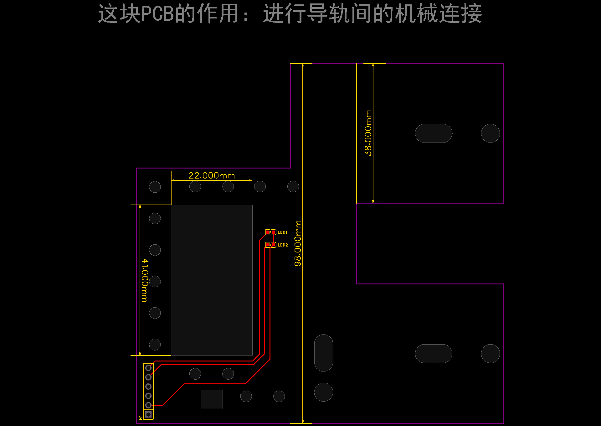
3.5 Mechanical Guide Rail Section

4 Detailed Principle Analysis (Software Section)
4.1 Software Repository
GitHub Project Address (Lower Machine ESP32): https://github.com/g122622/3-DIM-Motion-Platform-ESP32
GitHub Project Address (Upper Machine Web Interface): https://github.com/g122622/3-DIM-Motion-Platform


 京公网安备 11010802033920号

 HM31-30100


