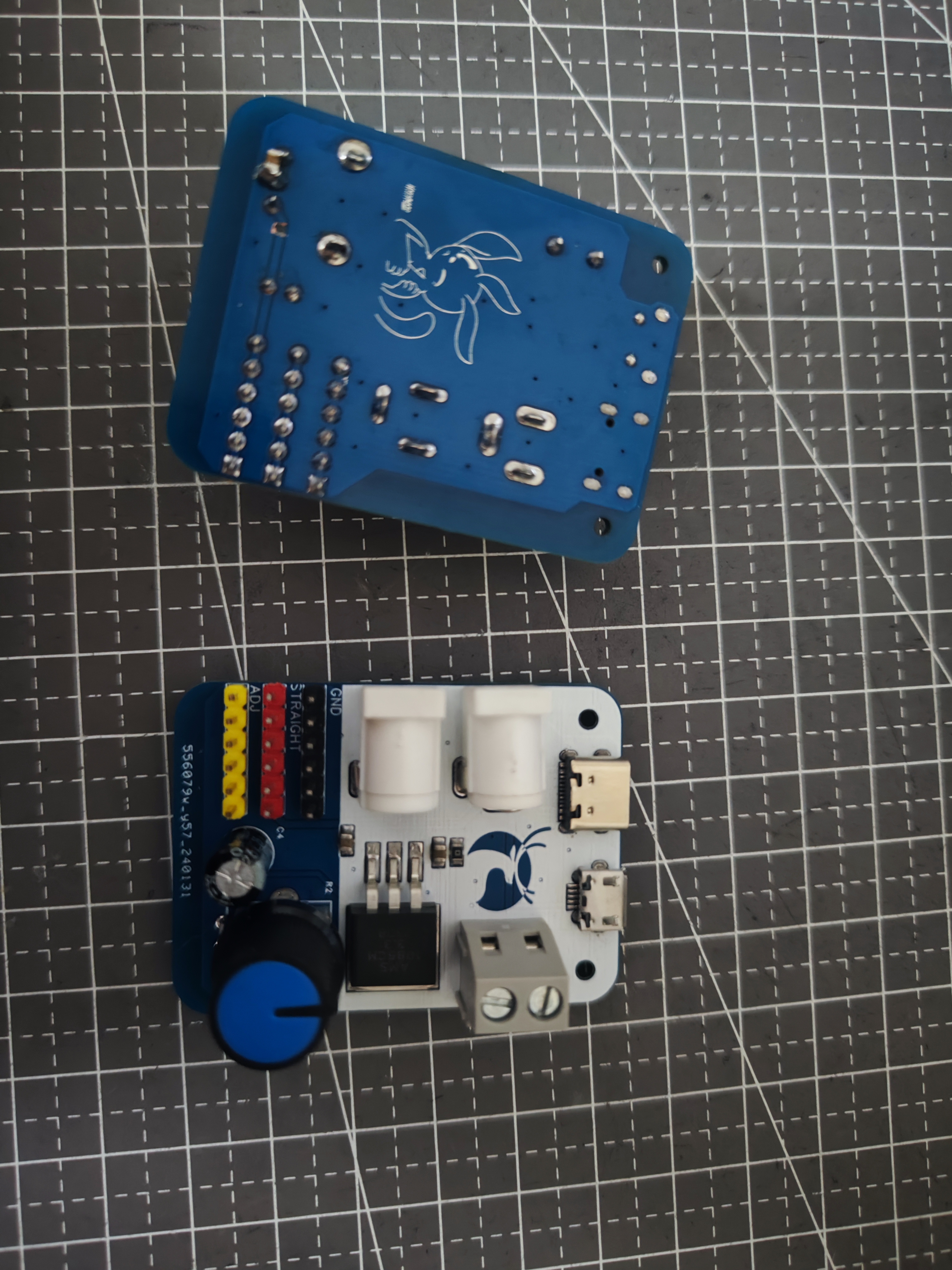
 I won't go into detail about disassembling the module; solder the adapter board. The wires are pin-to-pin; just solder them parallel to each other, as shown in the picture .
 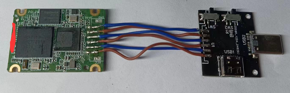 attaching the heatsink
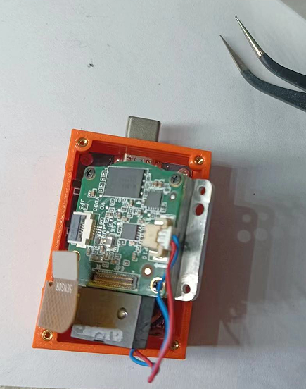
  and soldering, cover the front of the board with a layer of tape to prevent the components above from being knocked off during installation (don't ask me why I'm reminding you) .
  Clean off the supports
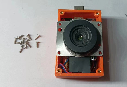
 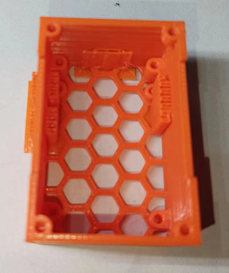 and then put on the knurled nuts. Install the motherboard
 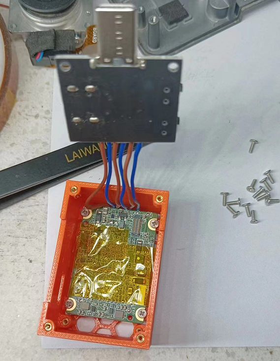 and then install the adapter board on top. This step requires some patience; be careful not to damage the components below, which is why you use tape.
 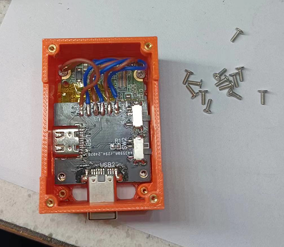 The rest is simple: install the ribbon cable. Note that there are two layers of foam at the shutter switch on the camera; remove them.
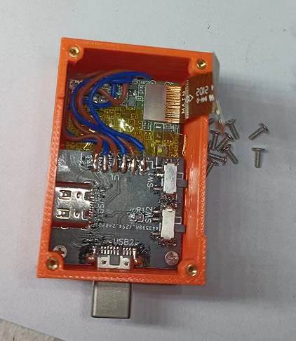
 Put the cover on and screw it in.
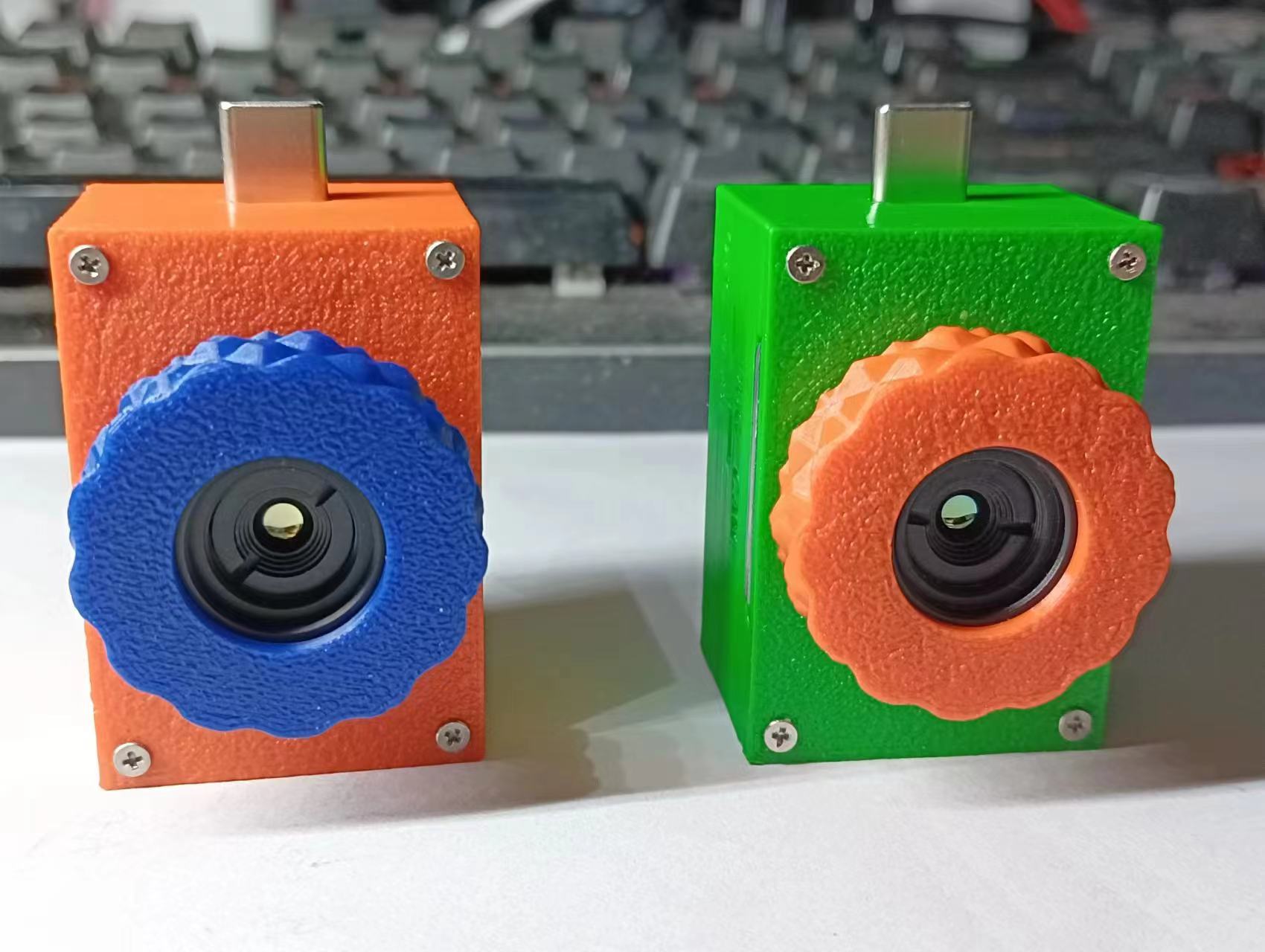
 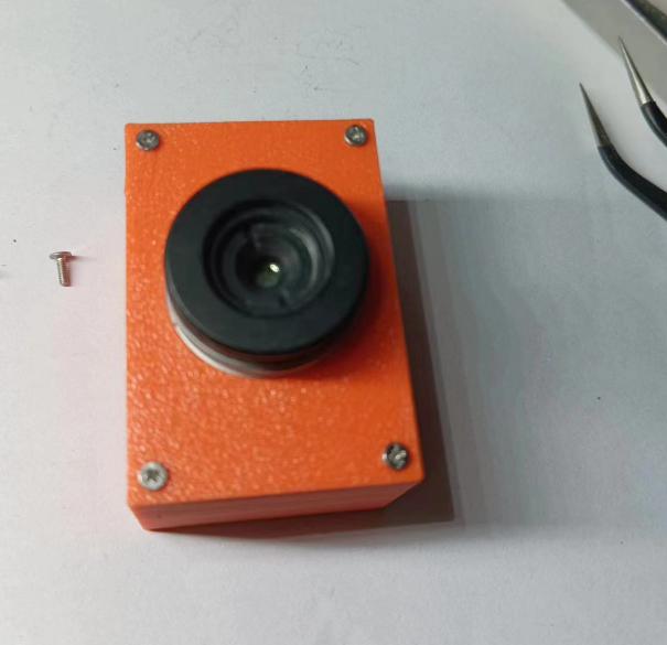 Use a utility knife to remove the adhesive from the lens, cleaning both sides until you can screw the lens in.
  Screw on the lens cap, and enjoy!

All reference designs on this site are sourced from major semiconductor manufacturers or collected online for learning and research. The copyright belongs to the semiconductor manufacturer or the original author. If you believe that the reference design of this site infringes upon your relevant rights and interests, please send us a rights notice. As a neutral platform service provider, we will take measures to delete the relevant content in accordance with relevant laws after receiving the relevant notice from the rights holder. Please send relevant notifications to email: bbs_service@eeworld.com.cn.
It is your responsibility to test the circuit yourself and determine its suitability for you. EEWorld will not be liable for direct, indirect, special, incidental, consequential or punitive damages arising from any cause or anything connected to any reference design used.
Supported by EEWorld Datasheet
EEWorld
subscription
account

EEWorld
service
account

Automotive
development
community

Robot
development
community

About Us Customer Service Contact Information Datasheet Sitemap LatestNews


Room 1530, 15th Floor, Building B,
No.18 Zhongguancun Street,
Haidian District,
Beijing, Postal Code: 100190
China
Telephone: 008610 8235 0740
 京公网安备 11010802033920号

 101C623U030BJ1BP


