I previously designed a popular floating ambient light, but after using it for a while, I found that the battery life seemed a bit short. After being alerted by netizens, I discovered that the LDO was continuously consuming power, and testing confirmed this. This was unacceptable, so I removed the LDO to optimize battery life in a new version.
Static power consumption testing,
using a multimeter connected in series between the battery's positive terminal and the PCB battery's positive terminal, showed that even when the ambient light was off, it still consumed about 4mA of current.
Checking the datasheet of the AMS1117 chip I used confirmed that the static current is 5-10mA.

Since this ambient light doesn't have a physical power switch, this issue needed to be addressed; otherwise, a 1000mAh battery would be dead after just one week.
The schematic was modified:
compared to the previous version, the new version removed the LDO, and the battery directly powers the LED filament.
This does cause a problem: as the battery voltage decreases, the brightness of the LED filament gradually decreases at the same brightness level, but this isn't a significant issue and doesn't affect usability.
Additionally, since the battery directly powers the LED filament, with a full charge voltage of 4.2V, the LED filament brightness will be significantly higher at maximum brightness compared to the 3.3V supply after using an LDO to step down the voltage. Therefore, the LED current-limiting resistor R11 can be increased accordingly.
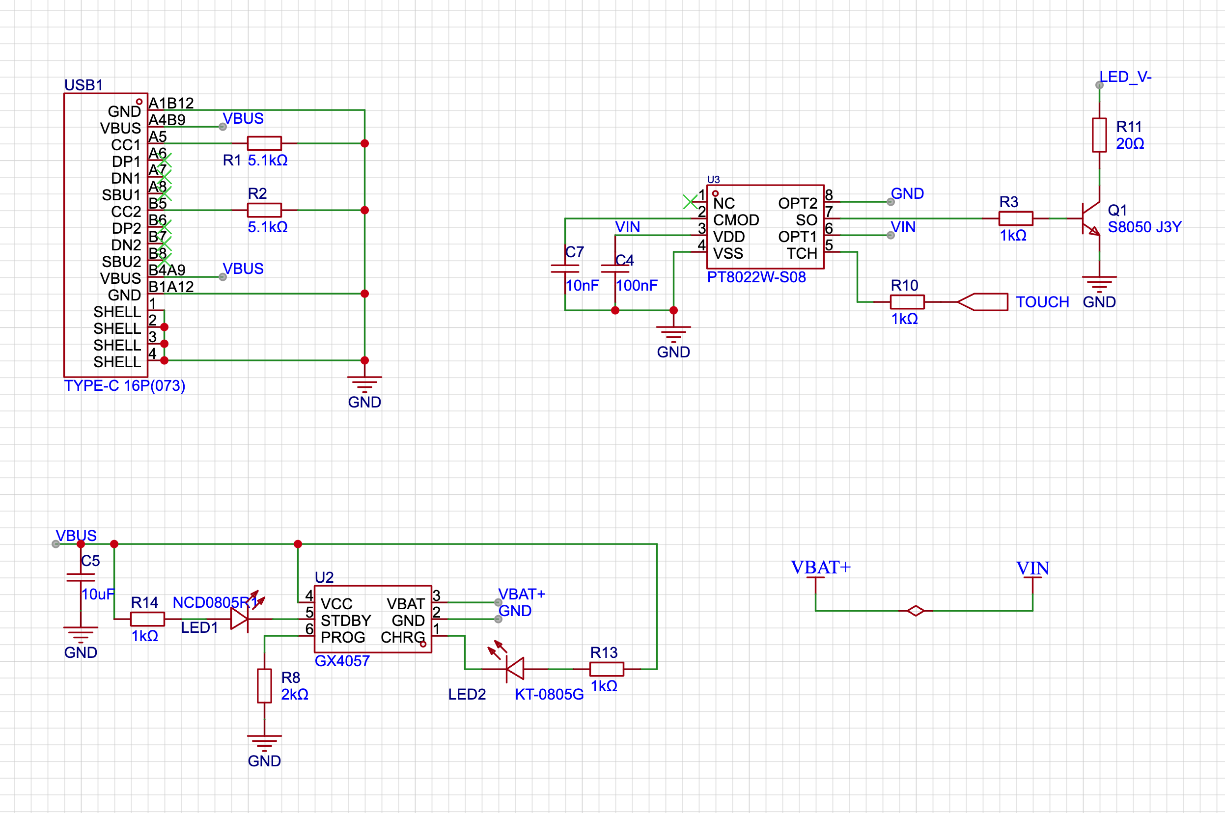
According to the PT8022W datasheet, the standby current is only a few μA, meaning that even without a physical power switch, the 1000mAh battery can provide a very long standby time.

Flexible filament ambient light.stl
PDF_Flexible Filament Ambient Light with Optimized Power Consumption.zip
Altium Flexible Filament Ambient Light - Optimized Power Consumption Version.zip
PADS_Flexible Filament Ambient Light - Optimized Power Consumption Version.zip
BOM_Flexible Filament Ambient Light - Optimized Power Consumption Version.xlsx
93584
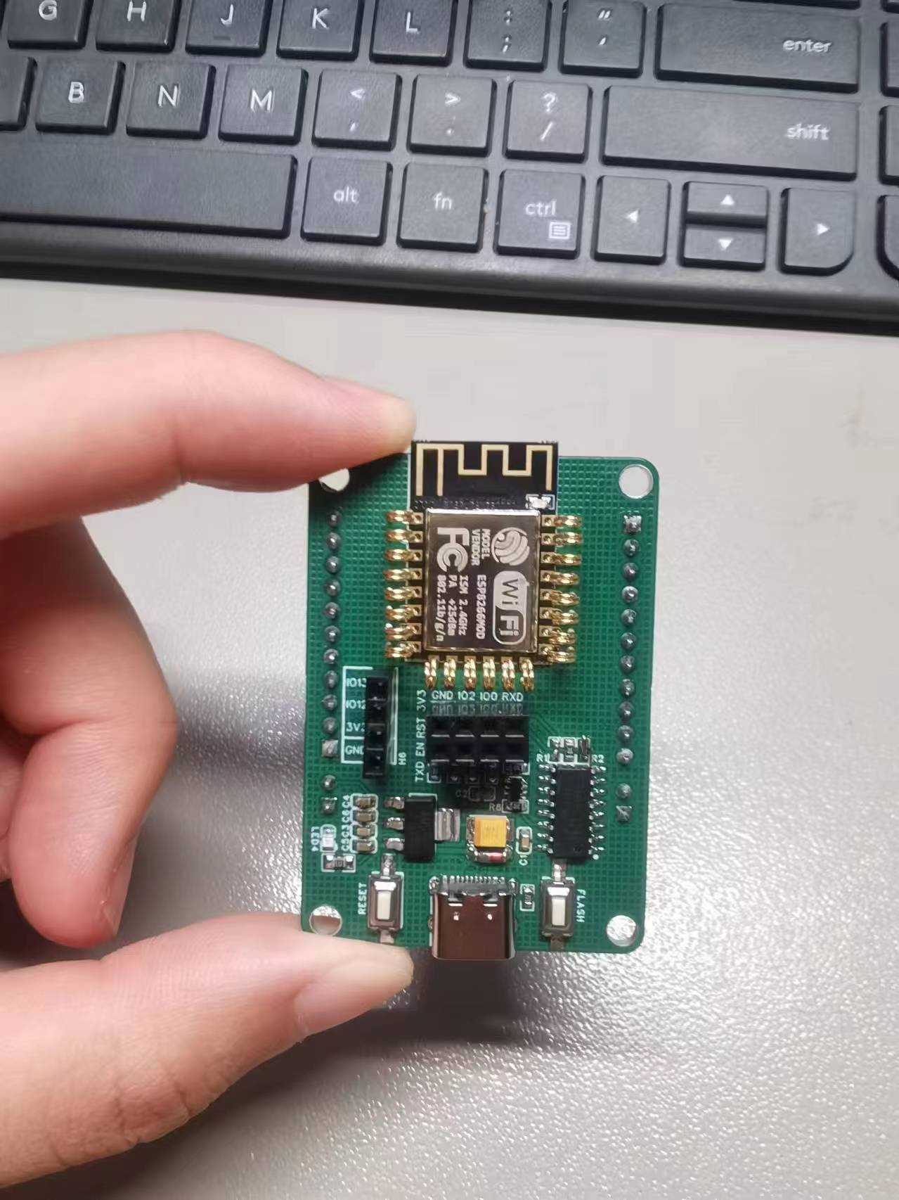
ESP8266 test programmer
The module allows for quick debugging, eliminating the need for soldering and improving fault tolerance. It features an automatic download circuit, a CH340C to serial port chip with all pins exposed, and a built-in OLED interface for easy programming and debugging. This work references similar projects from several other developers.
The description states
a desire for a full-featured ESP8266 programmer, but not a preference for the ones available online. The desired features include a Type-C interface, a pleasing design, a rich set of interfaces, and a user-friendly programming experience. Based on the following examples, a custom programmer was created, essentially a collection of examples : 2
*
4*2.54mm female headers, an IIC screen interface,
and
a single pin header on the back (they seem bulky with double rows of female headers on both sides). Automatic programming is referenced in the ESP8266 programming rack (JLCPCB EDA Open Source Hardware Platform (oshwhub.com) ). Thanks to all the open-source contributors! The test ring in the effect diagram was an idea proposed by luoxing. It uses pure copper pins. For the size 0 pin, the non-pin side needs to be cut off along the top. Then, during component insertion, insert the pointed end into the round hole. For positions R1/R2, since there are no 1k resistors, a lump of solder is used for connection; this does not affect functionality. For aesthetics, two LED pins could be added. The board mounting order is: pins, 2*4 female headers, 1*4 female headers, then pin headers.


PDF_ESP8266 Test Burner.zip
Altium_ESP8266 test programmer.zip
PADS_ESP8266 Test Burner.zip
BOM_ESP8266 Test Burner.xlsx
93585
A 5V 40A DC-DC module based on PW22ASAB
This DC-DC converter uses two PW22ASAB modules. It is primarily designed for multi-bay NAS enclosures, providing both 12V and 5V power to the hard drives, addressing the issue of insufficient 5V power supply from standard enclosure power lines. Suitable for setups with eight or more hard drives.
Function Introduction:
Two PW22ASAB connectors can provide a total of up to 40A of 5V power supply, fully meeting the needs of multi-bay hard drives. Recommended for use in environments with 8-16 drives (8-bay tested).
The layout
uses a 4-layer board. The top CN1 and CN3 are 12V input terminals, with the same wiring sequence as the 8-pin power cable for graphics cards.
Considering different usage environments, the output port wiring sequence needs to be carefully checked.
The bottom CN4, CN6, and CN5 are output ports, consisting of a two-pin 12V direct output, a two-pin 5V output, and a 4-pin GND
input. The CPU 8-pin 5569 connector (straight-through, solid pin)
and output ports are CPU 8-pin 5569 connectors (angled, solid pin).
Again, the output port wiring sequence needs to be carefully checked.
Filter Capacitors
: This module's input and output capacitors consist of 8 solid-state through-hole capacitors and 16 tantalum capacitors.
These capacitors also determine the module's ripple performance (and price); pay attention to the packaging and voltage rating when selecting them.
Ripple performance – Further
verification needed
. Verified; stable operation in 8-bay configuration.
PDF_5V 40A DC-DC Module Based on PW22ASAB.zip
Altium_5V 40A DC-DC module based on PW22ASAB.zip
PADS_5V 40A DC-DC Module Based on PW22ASAB.zip
BOM_5V 40A DC-DC Module Based on PW22ASAB.xlsx
93586
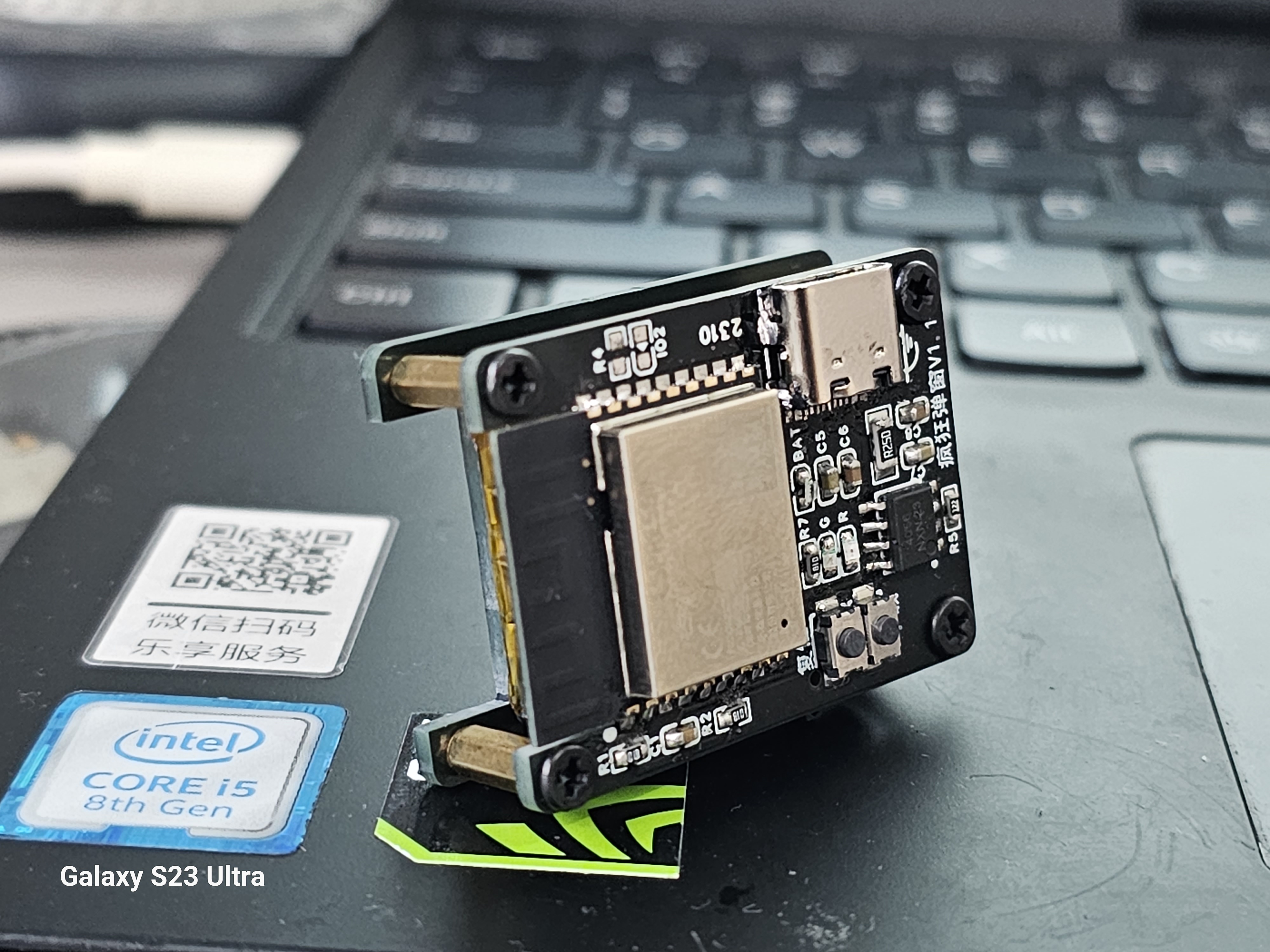
ESP32 C3 keeps displaying pop-up messages (onboard antenna)
Make your Apple device bombarded with pop-ups.
Uploading via VS Code
requires the latest version. Please visit:
https://oshwhub.com/qusenberg/feng-kuang-dan-chuang-pro
. For maximum power, add the following source code below `BLEDevice:init("Airpords69)"`: `
esp_ble_tx_power_set(ESP_BLE_PWR_TYPE_AD V, ESP_PWR_LVL_P21);
esp_ble_tx_power_set(ESP_BLE_PWR_TYPE_SC AN, ESP_PWR_LVL_P21);
esp_ble_tx_power_set(ESP_BLE_PWR_TYPE_DEF AULT, ESP_PWR_LVL_P21);
` Effective distance ≥ 3m.
Materials:
1) Thickness, width, and length 70, 20, 25mm; Battery - 300mA (antenna version is 150mA);
2) Copper pillars M2*8 (4 pieces), M2 screws (8 pieces).
3) 3M double-sided tape for fixing the battery
V1.0 (October 18, 2023):
1) Simplified the size of the ESP32 development board, and added a battery management module later for easy portability without external power supply;
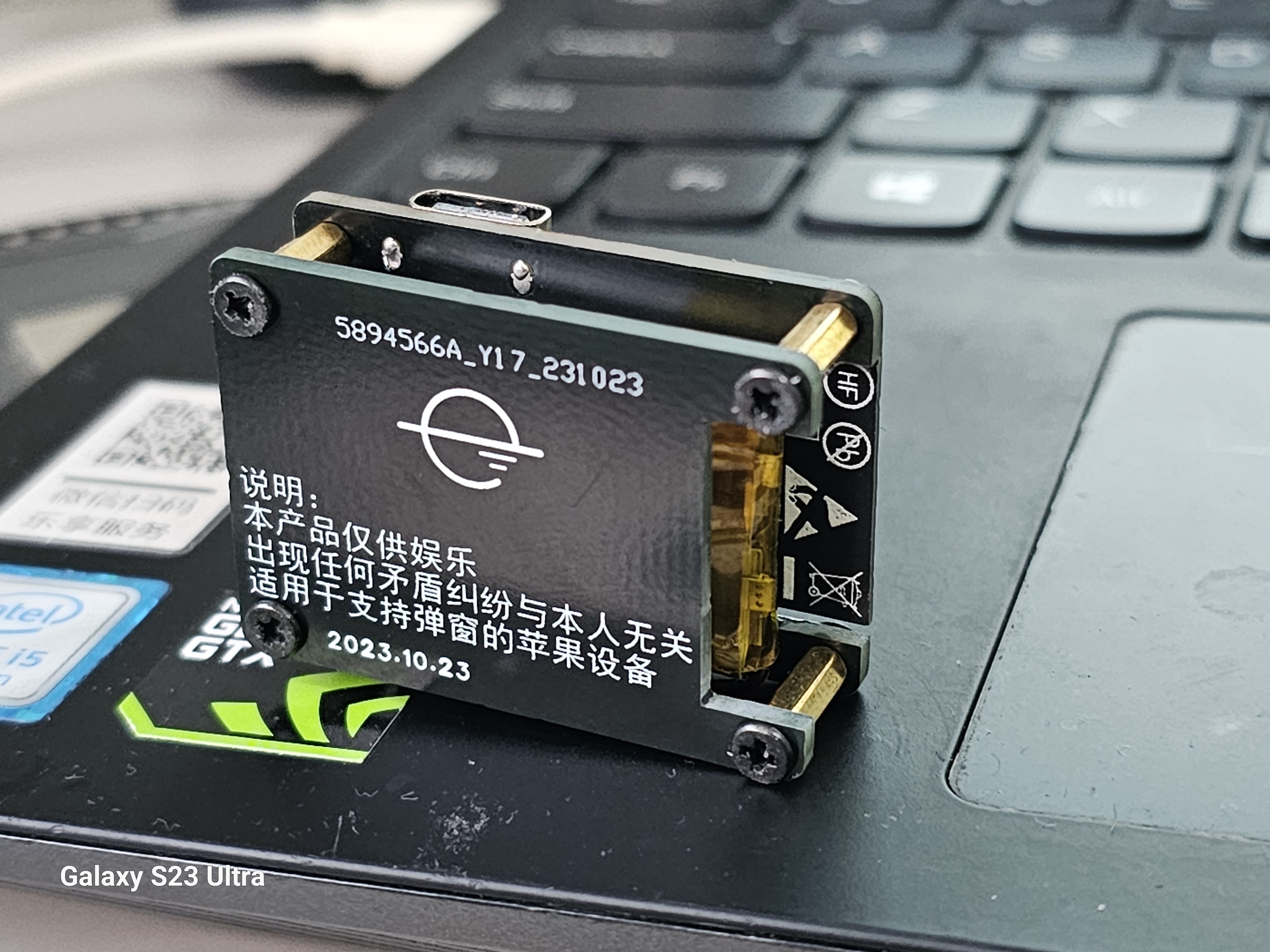
V1.1 (October 23, 2023) :
1) Changed ESP32 S3 to ESP C3 to reduce cost;
2) Added a power switch (forgot to mention, oops!);
V1.2 (October 24, 2023): 1
) Circuit fine-tuning;
V1.3 (November 4, 2023):
1) Added a step-down voltage regulator chip to solve the problem of program download failure without battery installation (useless); 2
) Added battery pads;
3) Circuit adjustments;

Protocol introduction:
BY: Attribution (
optional
) NC: Non-Commercial (optional ) ND: No Derivatives SA: ShareAlike Attribution BY. Anyone using your work must give appropriate attribution, provide a link to the corresponding CC license, and indicate whether modifications were made (to the original work). Non-Commercial Use NC. Others may not use your work for commercial purposes. No Derivatives ND. If someone remixes, transforms, or creates based on your work, they may not distribute the modified work. ShareAlike SA. If someone remixes, transforms, or creates based on your work, they must distribute the modified work under the same license as the original. Note: This product is for entertainment purposes only. Any disputes arising from it are not the responsibility of the user. Compatible with Apple devices that support pop-ups.
EvilAppleJuice-ESP32-C3.zip
esp32 Crazy Pop-ups.mp4
ESP32-C3 increases distance by more than 3m.zip
PDF_ESP32 C3 Crazy Pop-ups (Onboard Antenna).zip
Altium_ESP32 C3 Crazy Pop-ups (Onboard Antenna).zip
PADS_ESP32 C3 Crazy Pop-ups (Onboard Antenna).zip
BOM_ESP32 C3 Crazy Pop-ups (Onboard Antenna).xlsx
93587
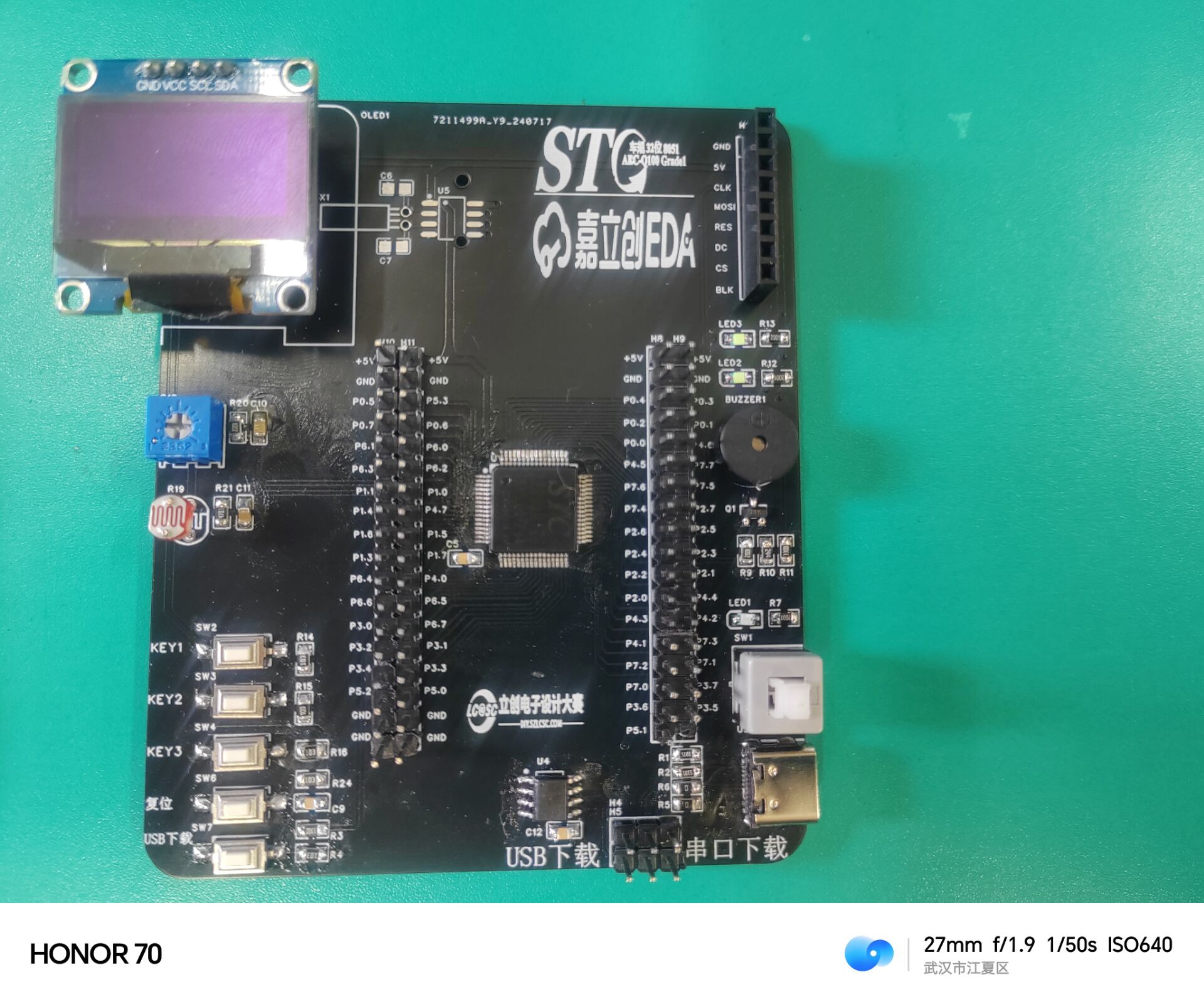
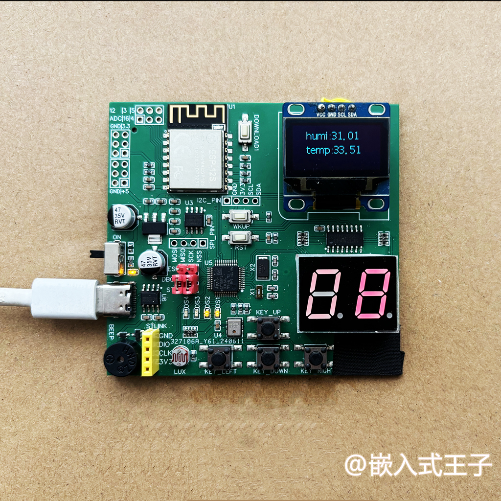
STC32G2K128 Development Board
STC32G128K microcontroller development board, 64 I/O ports
The STC32G128K microcontroller development board includes two LEDs, independent buttons, an I2C 4-line OLED display, an SPI 7-line TFT display, a 10K potentiometer, a photoresistor, a GN1302 real-time clock, a passive buzzer, supports USB and serial port downloading, and exposes all I/O ports.
QQ Video 20240723110658.mp4
1-1 Light up an LED.zip
PDF_STC32G2K128 development board.zip
Altium_STC32G2K128 development board.zip
PADS_STC32G2K128 development board.zip
BOM_STC32G2K128 development board.xlsx
93589
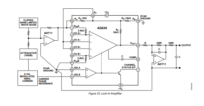
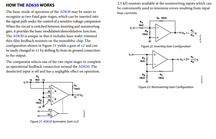
AD630 Lock-in Amplifier
The AD630 lock-in amplifier is a high-precision balanced modulator that uses a unique signal processing mechanism to extract target signals of specific frequencies and phases from complex signals.
The AD630 is a high-precision balanced modulator that combines a flexible commutation architecture with laser-tuned thin-film resistors for accuracy and temperature stability. Its signal processing applications include balanced modulation and demodulation, synchronous detection, phase detection, quadrature detection, phase-sensitive detection, lock-in amplification, and square wave multiplication. An on-board resistor network provides accurate ±1, ±2 closed-loop gain with an accuracy of 0.05% (AD630B). These resistors are used to precisely configure the multiplexer gain to +1, 2, 3, 4. Alternatively, external feedback allows designers to implement high-gain or complex feedback topologies.


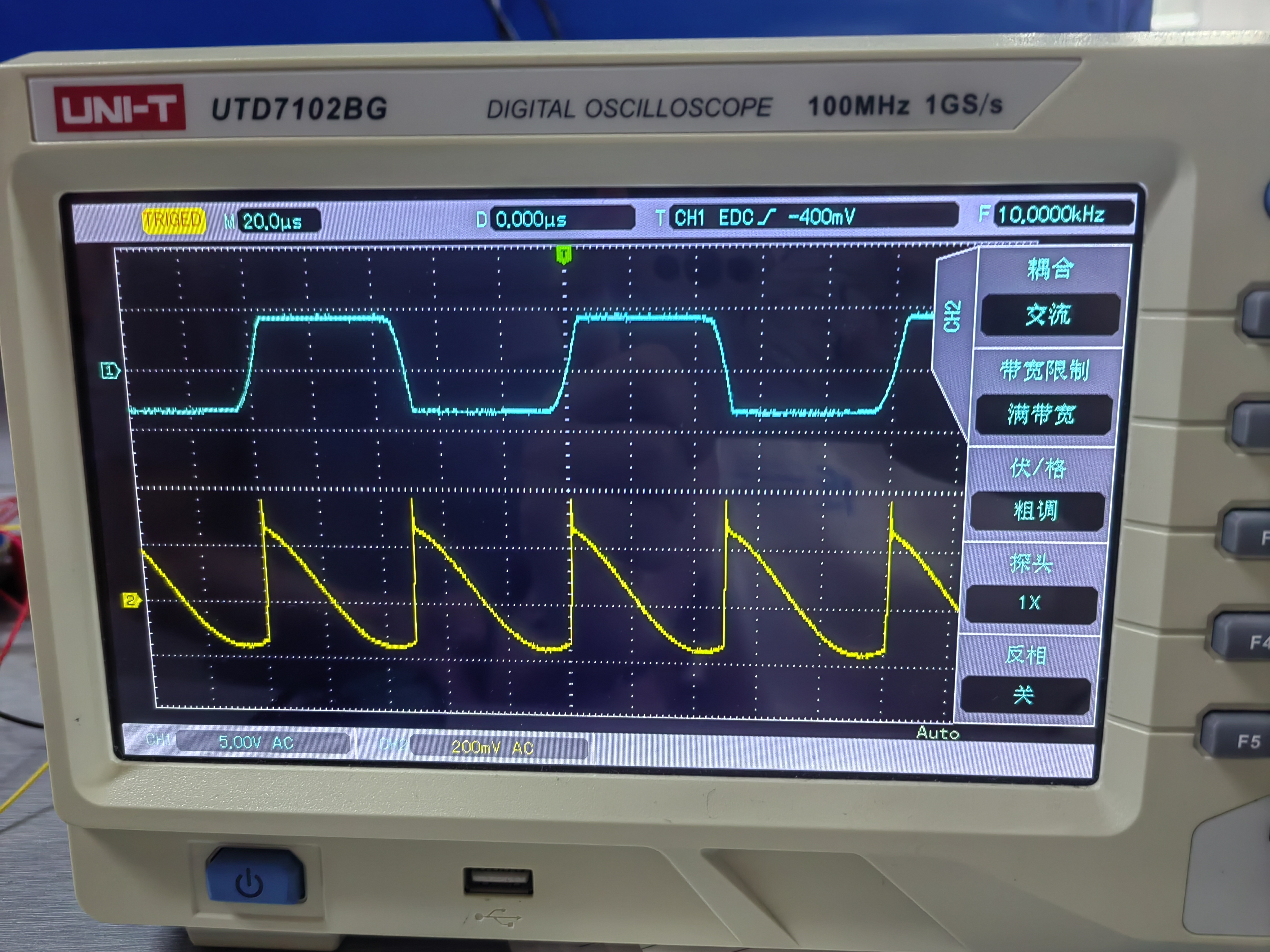
The following is a physical image:


AD630 Lock-in Amplifier.ms14
PDF_AD630 Lock-in Amplifier.zip
Altium AD630 Lock-in Amplifier.zip
PADS_AD630 Lock-in Amplifier.zip
BOM_AD630 Lock-in Amplifier.xlsx
93590
"32Pi_Zero" - Development board based on STM32F103+ESP
1. Objective: To design an inexpensive IoT development board with abundant peripherals, suitable for beginners;
2. Features: This development board has relatively rich basic peripherals, suitable for beginners and electronics enthusiasts;
3. Note: This solution has been tested on a pre-built board. Those without circuit knowledge should use it with caution.
I. Project Introduction:
Design a low-cost IoT development board with rich peripherals for teaching purposes. The board will be designed and developed using CUBE, combined with embedded operating systems such as FreeRTOS, to enable users to become familiar with bus and peripheral development.
II. System Features
: Main Control Chip: STM32F103C8T6;
WIFI Module: ESP12S (ESP8266 core)
; Functional
Peripherals : GPIO 4, LED
External Interrupt 4, KEY, PWM, BUZZ , I2C, OLED, U8G2, SSD1306 , I2C, EP2ROM, AT24C02 , SPI, Flash, LittleFS , W25Q16 Timer, Infrared Receiver (IR), ADC , Photoresistor, AUX, UART , WIFI , Arduino Development, ESP-12S (ESP8266) , GPIO, Digital Tube, Serial Data Transmitter (74HC595). III. Physical Demonstration . IV. Precautions: This system is powered by a Type-C interface, with a power supply voltage limit of 5V. V. Demo Videos: Various tutorials will be uploaded to Bilibili later: https://space.bilibili.com/26064574?spm_id_from=333.1007.0.0 VI. Open Source Repository : https://gitee.com/watsonhuang/32pizero
6b79ecc6b400e5bc9d95cc61ff667587.mp4
f0e4505f783461774ec32c2ea60885c7.mp4
PDF__32Pi_Zero_-Development board based on STM32F103+ESP.zip
Altium__32Pi_Zero_-Development board based on STM32F103+ESP.zip
PADS__32Pi_Zero_-Development board based on STM32F103+ESP.zip
BOM__32Pi_Zero_-Development board based on STM32F103+ESP.xlsx
93591
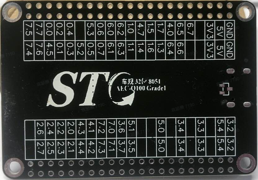
STC32G12K128 Development Board
Microcontroller Creative Design Competition, STC32G12K128 Development Board
The STC32G12K128 core board is also compatible with the STC8H8K64U chip. It features one onboard EEPROM and one NOR flash.
Firmware can be easily downloaded by connecting the core board to a computer.

The back of the board includes pinouts and the STC logo.
STC32G12K128.mp4
LED Test Program.zip
PDF_STC32G12K128 development board.zip
Altium_STC32G12K128 development board.zip
PADS_STC32G12K128 development board.zip
BOM_STC32G12K128 development board.xlsx
93592
Mornsun Auxiliary Power Supply
This project uses an auxiliary power supply module based on Mornsun's URD480512YMD-10WR3. Essential for the electronics design competition!
This project uses the auxiliary power supply module based on Mornsun's URD480512YMD-10WR3, LCSC online store number (C6731983), with an input range of 18-75V (if such a wide input voltage range is not required, the URB series can be used instead, which will be much cheaper). It includes an onboard RT9013 to convert 5V to 3.3V.
Students participating in electrical engineering competitions can refer to this design to avoid the hassle of designing their own auxiliary power supply.
PDF_Mornsun Auxiliary Power Supply
Altium_Mornsun Auxiliary Power Supply.zip
PADS_Mornsun Auxiliary Power Supply.zip
BOM_Morsun Auxiliary Power Supply.xlsx
93593
electronic


 京公网安备 11010802033920号

 ST7271J1


