1. Function Introduction
This project uses the JLCPCB CW32 development board to design and fabricate a voltage and current meter. Currently, it can
measure voltage, current, capacitance, and resistance with high accuracy.
2. Schematic Diagram Description
2.1 Power Supply Circuit
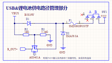
Considering the portability and ease of use of the voltage and current meter, a USB + lithium battery power supply scheme is adopted. When the USB socket is plugged in, the system is powered by the USB and charges the lithium battery; when the socket is unplugged, the entire power supply is provided by a single 18650 lithium battery.

2.2 Automatic Switching of Power Supply Circuit
The key to achieving automatic switching of the power supply circuit lies in the use of a PNP MOSFET. When the MOSFET's voltage is Vgs0, it is cut off, and the lithium battery does not supply power. When only the lithium battery is supplying power, point G is grounded, and the voltage is 0V.
2.3 5V Boost Circuit
Although lithium battery power is convenient, the battery voltage cannot reach 5V, and it will further decrease with use. Therefore, a boost chip is needed to boost the voltage to 5V. The boost converter chip used in this project is the X4310 from Chipstar. This chip has a fixed output of 5V when the input is 2.7~5V, and it also has current limiting protection—when the output current exceeds 300mA, the chip will limit the current to 300mA, ensuring the safety of the entire system.
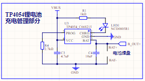
2.4 Lithium Battery Charging and Discharging Management Circuit
Regarding the lithium battery charging and discharging circuit, the commonly used TP4054 charging and discharging management chip was used. It has a maximum charging current of 500mA, which can be adjusted by changing the resistor. During charging, pin 1 of the chip is grounded, and the LED lights up. When the battery is fully charged, pin 1 switches to a high state, and the LED turns off. The battery charging status can be determined by the LED's on/off state.
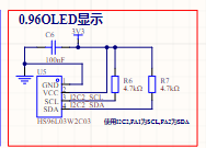
2.5 Display Circuit:
The display circuit uses a 0.96-inch OLED screen. This screen communicates via I2C, requiring only 4 pins to achieve real-time data display, significantly reducing I/O resource usage.
2.6 Key Control Circuit:
Key recognition in this project uses an interrupt-driven approach. A 100nF capacitor is added around each key for filtering and debouncing. Verification has shown that this method provides high accuracy in key detection, preventing issues like unresponsive keys or double-clicks when a single key is pressed.

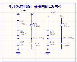
2.7 Current and Voltage Sampling Circuit:
The voltage sampling circuit uses a 1% accuracy voltage divider resistor to divide the voltage before it enters the MCU's ADC acquisition port. Diodes D3 and D5 limit the voltage here, preventing high voltage from entering the acquisition port and damaging the MCU. During voltage sampling, the voltage is first attenuated by 21 times before being acquired by the MCU's ADC pin and compared with an internal reference voltage. The output voltage value is then determined (if the output is less than 3V, a 2x attenuation channel is switched for re-conversion to improve measurement accuracy). The internal reference voltage is selected as 1.5V; the current sampling is similar, except that the resistor in the voltage attenuation circuit is replaced with a 100mΩ sampling resistor, and the circuit current is obtained by reading the voltage of the sampling resistor using an ADC.
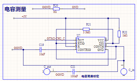
2.8 Resistance and Capacitance Measurement
This resistance and capacitance measurement utilizes the principle of NE555 square wave generation. First, the capacitor and resistor to be measured are connected to the NE555 circuit, causing the NE555 circuit to output PWM waves of different frequencies. Then, the PWM waveform frequency is captured using the CW32 input capture function. Finally, the values of the resistor and capacitor to be measured are calculated. The specific calculation steps are as follows:

The above figure shows the wiring diagram when the NE555 generates a square wave. The formula for calculating the frequency and duty cycle of the square wave is as follows (period: T, frequency F, duty cycle: D):
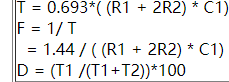
Therefore, to measure capacitor C1, it is only necessary to control R1 and R2 to constant values and calculate according to the PWM frequency F captured by the MUC. The formula is: C1=1.44/(R1+2*R2)*F).
Similarly, the value of resistor R2 can be calculated using the formula: R2=1.44/(2*F*C1)-R1/2.
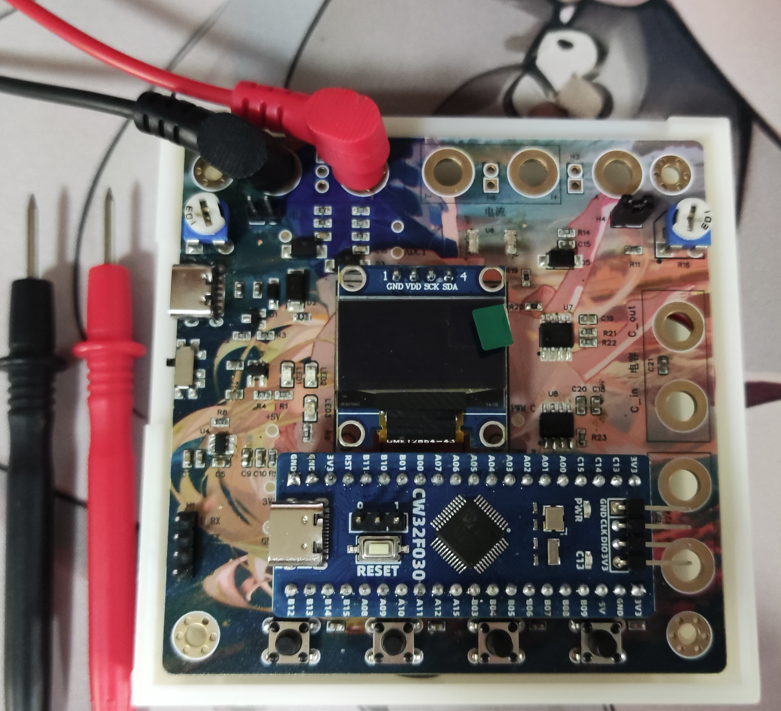
3. Physical Diagram
4. PCB Design Notes
In the PCB design, the power supply traces should be thickened, and copper pours should be used for connection when necessary.

When designing the current testing circuit, considering that the path will pass through a maximum current of 3A, it is essential to use full-connection copper plating on the pads, and the copper width must be wide to prevent the PCB from overheating due to high current, which would affect measurement accuracy.

5. Key Program Descriptions
5.1 Button Recognition Interrupt Configuration

When initializing the IO port, it is necessary to configure the external interrupt trigger condition and then enable the external interrupt.
Interrupt Service Function:

In this project, all GPIO ports share one interrupt service function. The function determines which IO port to interrupt and updates the flag bit.
5.2 ADC Configuration

In ADC conversion, three ADC ports are required. Therefore, multi-channel conversion is necessary when configuring the ADC, and it is important to ensure that the corresponding ADC conversion channel is enabled.
5.3 Timer Configuration
Timers were used for both resistor and capacitor tests. The timer configuration is as follows:
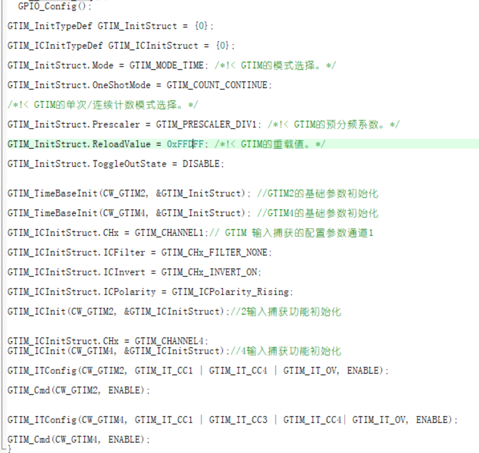
Initially, one timer with two channels was used to complete the input capture, but it was found that the same timer input capture interrupt start flag only had one bit, which could not capture two PWM waves of different frequencies simultaneously.
Ultimately, two timers were used.
6. Material Purchase
In this project example, all materials can be purchased from LCSC Mall. LCSC Mall is recommended!
7. Assembly Instructions:
All resistors and capacitors in this project use 0603 packages. Beginners can easily replace them with plug-in packages to reduce soldering difficulty. The casing and PCB are fixed with 4 M3 screws. The 18650 lithium battery is placed inside the casing.


 京公网安备 11010802033920号

 240-0323-25PPE4K1-18M1


