This is an open-source replica of the [LCSC Taishanpai Development Board] small mobile phone project.
1. The main control core board
uses the Taishanpai Development Board as its core board.
The CPU is an RK3566, a quad-core Cortex-A55, with a main frequency of 1.8GHz, an NPU with 1.0 TOP computing power, and supports 4K 60fps video decoding.
2. The display
uses a 3.1-inch LCD touch screen from Daxian Weiye Technology.
The display interface is MIPI, and the touch interface is I2C.
3. The
speaker uses a 2809 model rectangular speaker.
4. The microphone
uses a B4013AM423-008 model microphone.
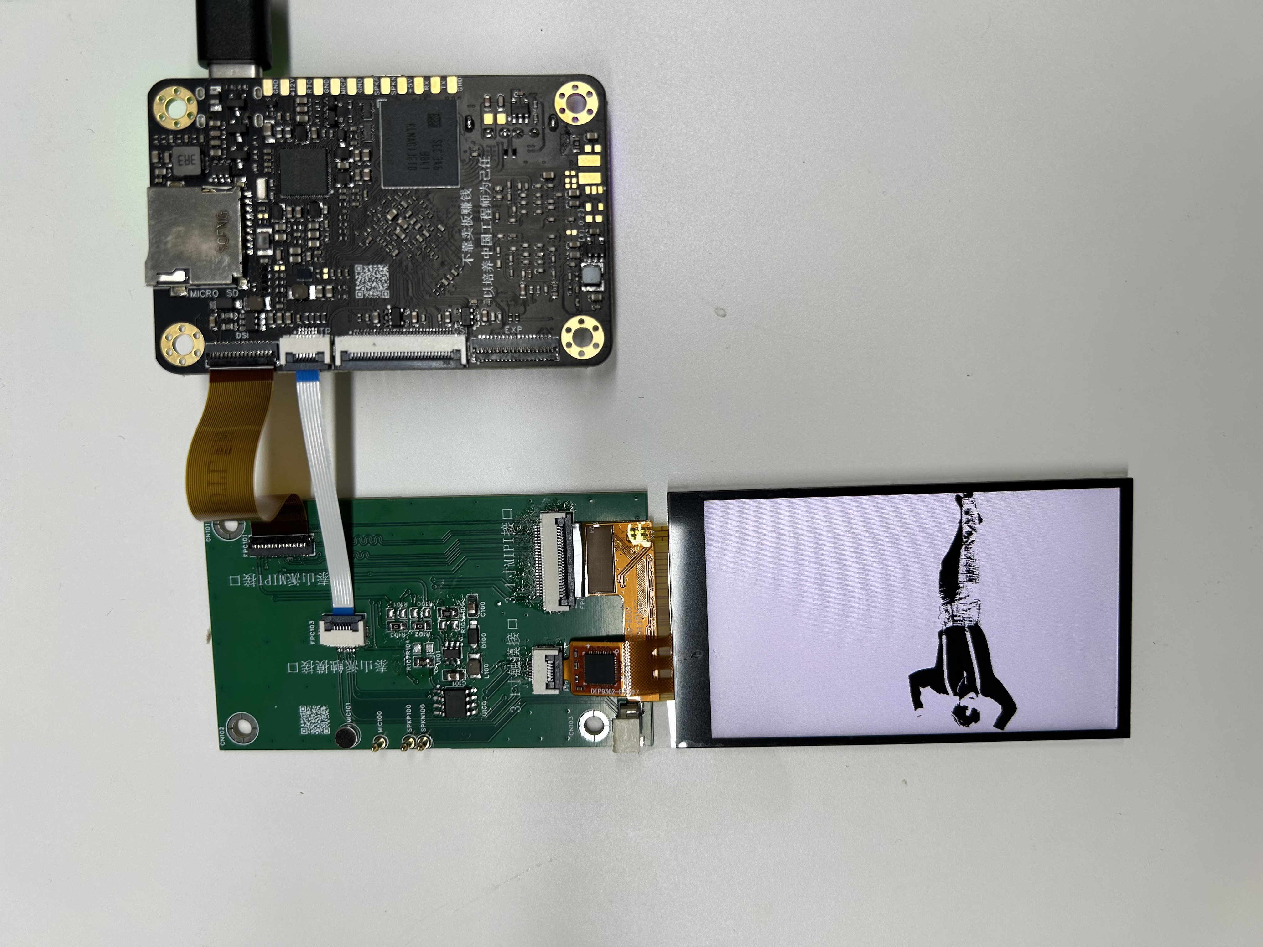
Physical demonstration
! [IMG_2261.jpeg]
Bill of Materials.png
Top Shell.STL
Bottom shell.STL
IMG_2265.mov
Altium-based small mobile phone project using the LCSC Taishanpai development board. (zip file)
PADS_Based on the [LCSC Taishanpai Development Board] Small Mobile Phone Project.zip
BOM_Based on the [LCSC Taishanpai Development Board] Small Mobile Phone Project.xlsx
94647
A small mobile phone project based on the [LCSC Taishanpai Development Board]
Using the Taishan School as the core board, an expansion board is made.
The expansion board is based on the official expansion board and the Cat Screen adapter board.
Initially, it was envisioned for use as a TV box or NAS, but the software is still not complete...
It includes three Type-A ports, one Type-C port, one 3.5mm audio jack, one SATA port, one infrared port, and two external headers for expansion.
The connection diagram is
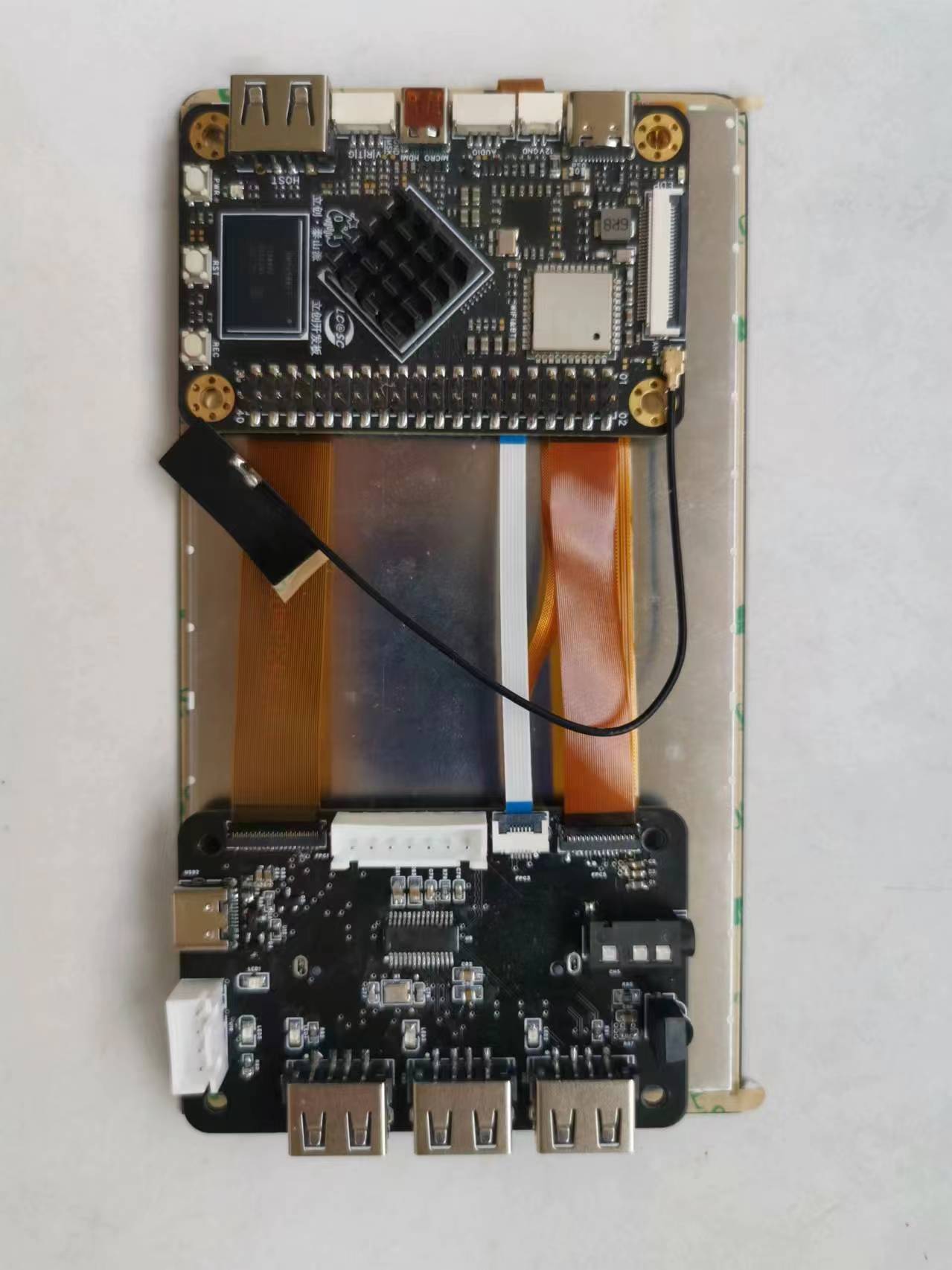
attached; the Debian system
shell was just printed and hasn't arrived yet.

PDF_Small mobile phone project based on the [LCSC Taishanpai Development Board].zip
Altium - A small mobile phone project based on the LCSC Taishanpai development board.zip
BOM_Small Mobile Project Based on [LCSC Taishanpai Development Board].xlsx
94649
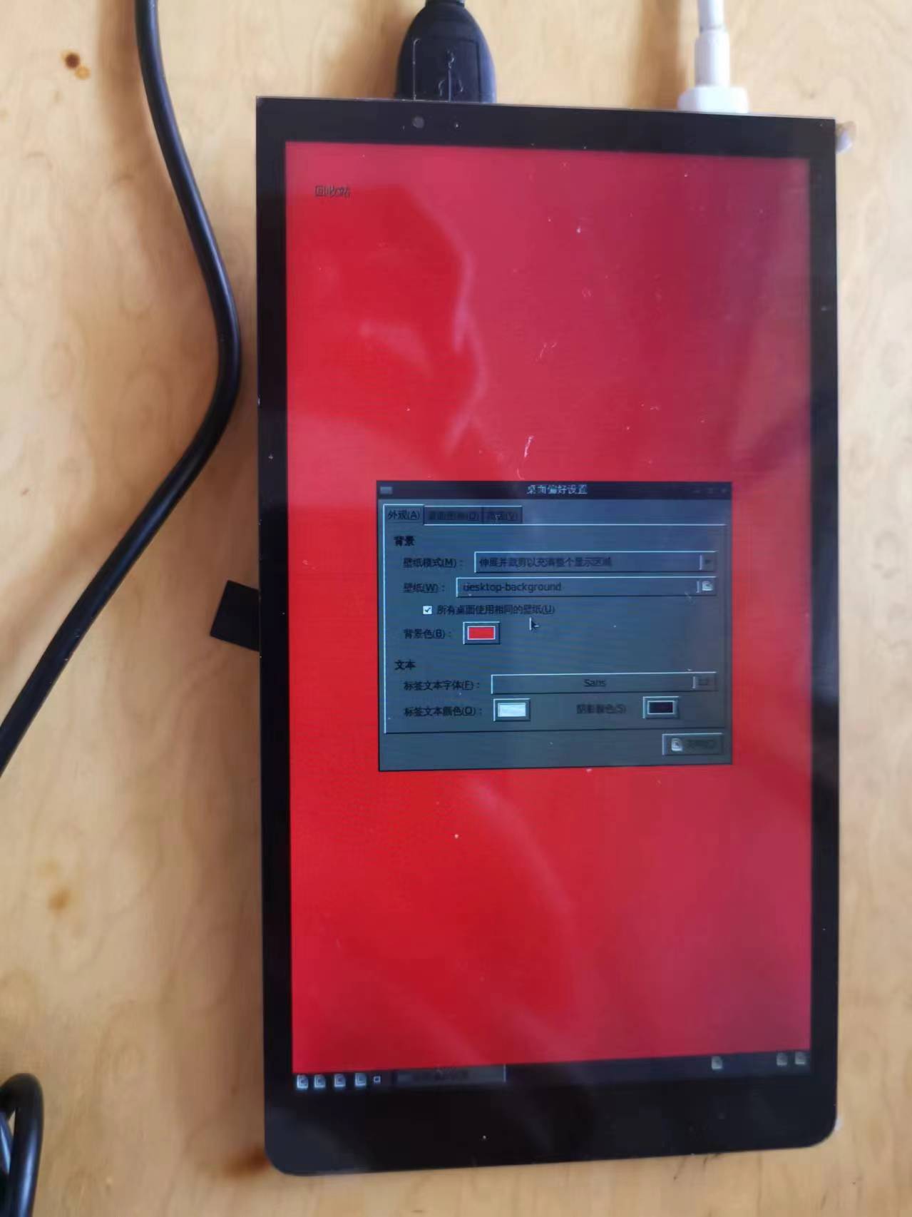
Smartphones based on the [LCSC-Taishanpai Development Board]
Design a smartphone based on the RK3566 chip, driving the MIPI screen and backlight hardware circuitry.
This design is for a smartphone, utilizing the RK3566 platform and displaying via a MIPI interface. I learned a great deal from the platform and Mr. Wu during this project. This included setting up the environment, porting and compiling the Android SDK project, and writing the underlying communication driver myself. The platform also provided many ways to create physical prototypes, such as the free PCB prototyping activity on the JLCPCB platform and the creation of 3D models. I am extremely grateful for the platform's activities, which allowed me to rediscover the design spirit I had longed for since leaving school.
1551188819-1-16.mp4
PADS_Based on the [LCSC-Taishanpai Development Board] Smartphone.zip
BOM_Based on [LCSC-Taishanpai Development Board] Smartphone.xlsx
94650
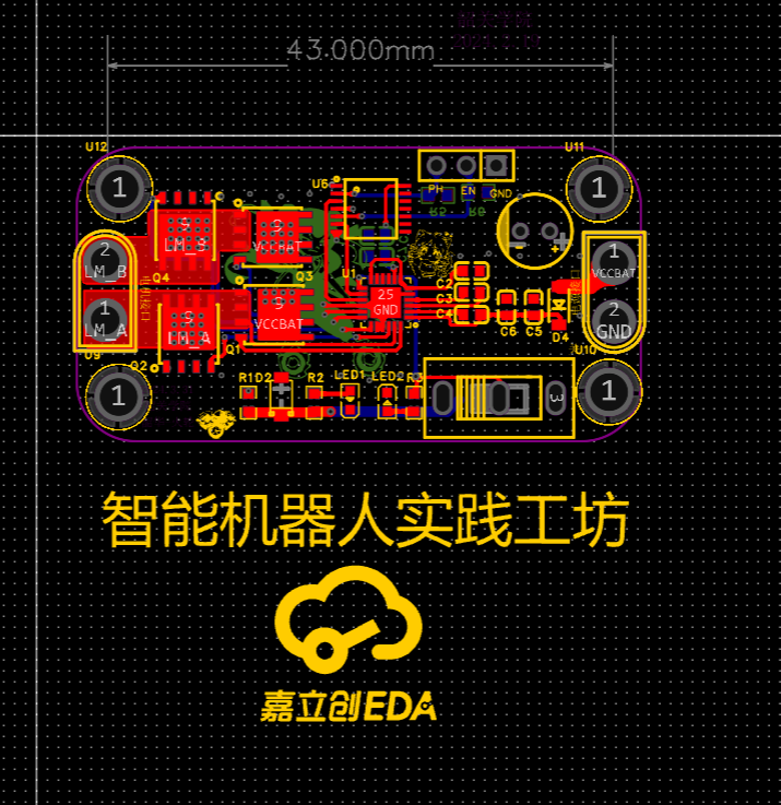
Single DRV - Shaoguan University
drive
This project involves the design of a DRV8701 driver board to drive a brushed motor.

The PCB
layout is within 10*10mm. For
trace spacing, large copper areas are used for high-current components; power lines are 30mil, and signal lines are 10mil. During
circuit debugging
and soldering, the switch and each power module are soldered first, with one module soldered at a time for testing. This ensures each module functions correctly and facilitates troubleshooting.
The project summary notes
some layout issues, with components too close together. Some desoldering is difficult.
The layout is somewhat fragmented. The traces are not aesthetically pleasing.
The soldering is rather unsightly and requires more practice.
Some components are obscured.
As a university student with limited technical skills, please point out any errors.
PDF_Single DRV-Shaoguan University.zip
Altium_Single DRV-Shaoguan University.zip
PADS_Single DRV-Shaoguan University.zip
BOM_Single DRV-Shaoguan University.xlsx
94651
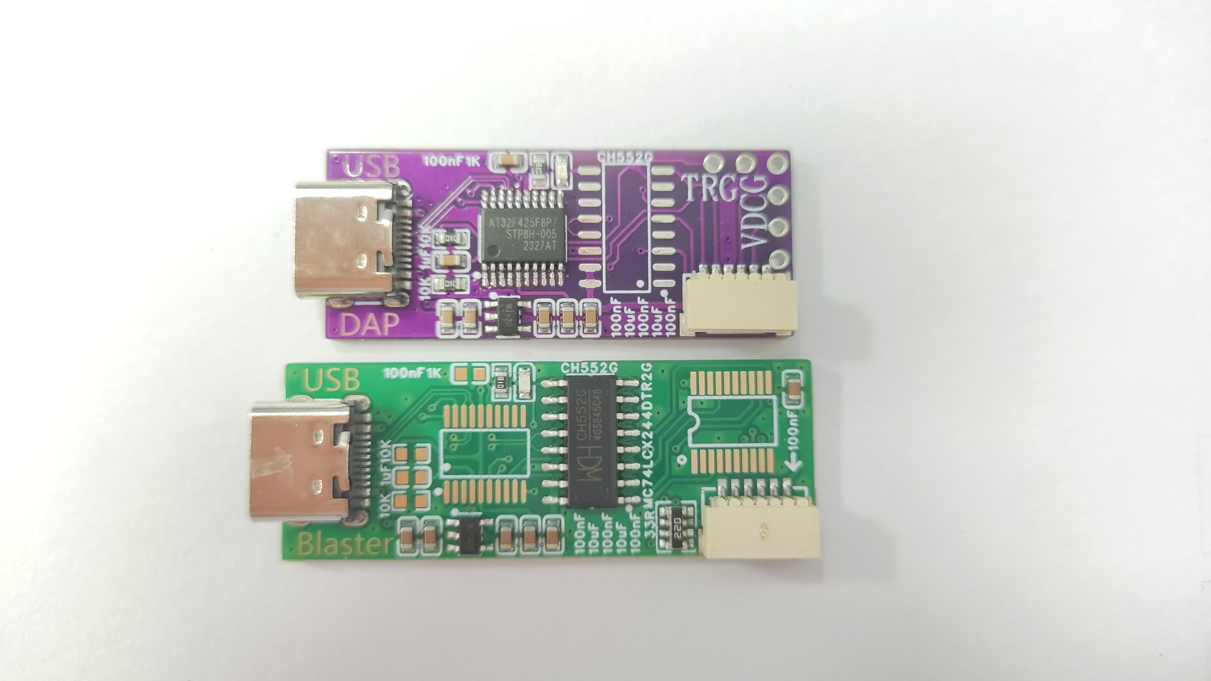
CMSIS-DAP
CH552AT32F425 compatible DAP solution
The CH552AT32F425 is compatible with the DAP solution; either one can be soldered.
Reference links: https://oshwhub.com/xivn1987/daplink, https://oshwhub.com/lengyuefeng/a7c57e6d86bd47789178df3fda9219dc
Firmware source code: https://github.com/XIVN1987/DAPLink
When using the AT32F425 solution, do not solder: U7, SW1, SW2, C23, C28, R8.
When using the CH552G solution, do not solder: U8, R6, R7, C26, C27.
Programming has been tested and works.
DAPLink-master.zip
PDF_CMSIS-DAP.zip
Altium_CMSIS-DAP.zip
PADS_CMSIS-DAP.zip
BOM_CMSIS-DAP.xlsx
94652
electronic


 京公网安备 11010802033920号

 1278358-1


