Today, with highly modern living standards, vacuum cleaners have become an essential small household appliance for smart homes that clean the home. The vacuum cleaner is a modern cleaning tool that uses the operating principle of a motor to run at high speed to form negative air pressure, making the dust box partially vacuum, thereby adsorbing dust particles to complete cleaning. It is mainly composed of three parts: dust collection, dust collection, and dust filtration. This article briefly introduces the application example of sensorless sine wave drive technology based on MM32SPIN25 in "handheld vacuum cleaner".
Program features:
ARM Cortex-M0 high-performance motor driver chip
Main frequency up to 96MHz
Built-in 32-bit hardware divider
Built-in multiple sets of comparators and operational amplifiers
180 degree sensorless sine wave drive
The motor speed can reach 100000rpm (2-pole motor)
The speed command input can be an analog voltage or PWM signal, and the actual speed can be fed back by FG
Constant speed or constant power operation
Supports multiple data communication interfaces: UART IIC SPI
Complete protection mechanism: over-current protection, over-voltage protection, under-voltage protection, over-temperature protection, stall protection, air inlet blockage protection
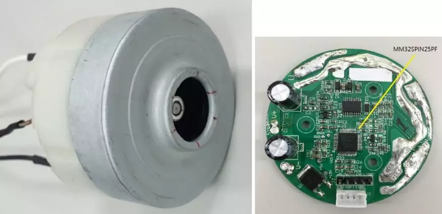
Figure 1. Left : Common 25.2V/380W handheld vacuum cleaner motor ;
Right picture : Driver board using MM32SPIN25PF
2. Principle of sensorless sine wave drive technology
This article introduces the technical principles and implementation methods of sensorless sine wave drive.
Figure 2 below is the control block diagram of the sinusoidal magnetic field guided drive motor. At the beginning of the process, the target speed command is read from the external input signal. After calculation by the closed-loop acceleration slope controller, the speed command that can be provided by the speed PI controller is obtained. Then, this speed command and the feedback actual speed are used through the PI controller. After calculation, the torque current command Iq is generated.
After the field-oriented controller (FOC) function block receives the torque current command and the estimated angle of the motor, it undergoes three-phase current feedback, coordinate conversion, current loop PI calculation, and space vector modulation (SVPWM) and other rule operations, as follows: This obtains the three-phase PWM duty cycle data required to approach the target speed, and then generates a PWM output from this data to an external electric drive component to drive the motor.
In the process of generating PWM signals by the magnetic field steering controller functional block, the sliding mode estimator (SMO) functional block is responsible for generating the estimated angle and speed required for motor operation.
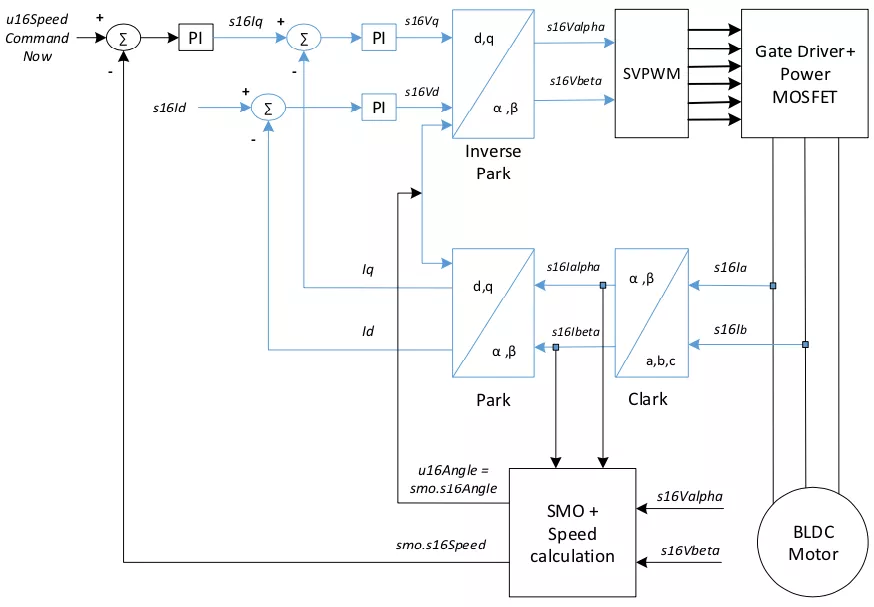
Figure 2. Sensorless sinusoidal magnetic field guidance ( FOC) software control block diagram
Figure 3 below is a detailed block diagram of the sliding mode angle estimation system. The sliding mode angle estimator consists of four main functional blocks. First, the estimated current is generated by the current estimator, and the difference between the estimated current and the measured actual currents Ialfa and Ibeta is used. After the bang-bang control and low-pass filtering function blocks are calculated, the estimated BEMF voltage value is generated. Ealfa, Ebeta, the estimated rotor angle can be obtained by calculating the arctangent of this estimated voltage value.
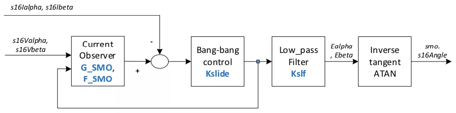
Figure 3. Sliding mode estimation (SMO) rotor angle estimation software control block diagram
The field-oriented control (FOC) of this scheme mainly has three coordinate transformation calculations, Clarke transformation, Park transformation and inverse transformation Park transformation. The purpose is to be able to control the magnetic field current Id and torque current Iq of the motor to achieve the speed control of the motor. This theory was proposed by F. Blaschke in 1972.
Clarke coordinate conversion:
The purpose is to convert the three-axis (a, b, c) coordinate system of the three-phase current into a 2-axis coordinate system. The following formula is the Clarke coordinate conversion equation.
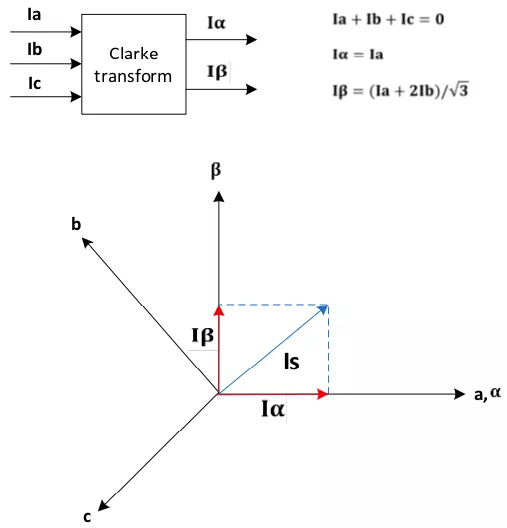
Figure 4. Clarke coordinate transformation and its equations
Park coordinate conversion:
Convert the static 2-axis coordinate system into a 2-axis (d, q) coordinate system for synchronous rotation of the motor. The d-axis represents the direction and magnitude of the rotor flux current, and the q-axis represents the torque current. The following formula is the Park coordinate conversion equation.
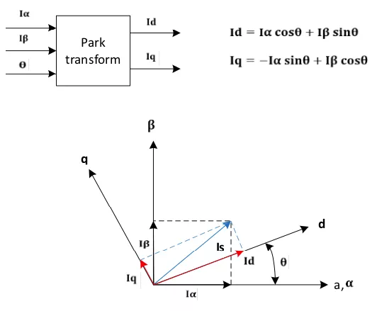
Figure 5. Park coordinate transformation and its equations
Inverse transformation Park 's coordinate transformation:
Convert the 2-axis (d, q) coordinate system of the motor's synchronous rotation back to the static 2-axis coordinate system. The following formula is the coordinate conversion equation of the inverse Park transformation.
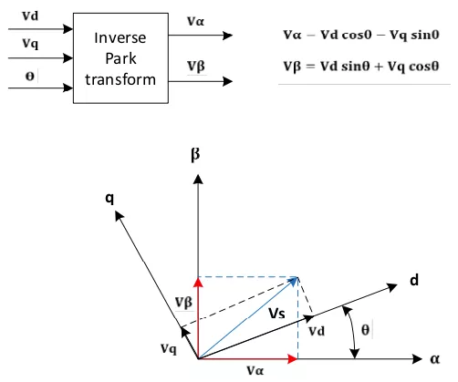
Figure 6. Inverse Park coordinate transformation and its equations
3.Hardware design
The built-in comparator and operational amplifier of MM32SPIN25PF simplify the design of the motor driver board. The reference schematic diagram of the handheld vacuum cleaner motor driver board is as follows:
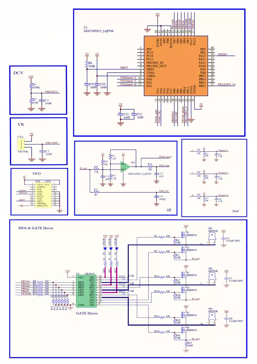
Figure 7. Handheld vacuum cleaner based on MM32SPIN25PF
Motor drive board schematic diagram
4. Phase current waveform driven by sinusoidal wave
This application case uses 180-degree sine wave drive. The phase current waveform under 300W operation is as follows:
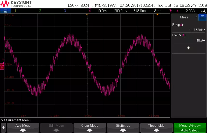
Figure 8. Sinusoidal phase current waveform under 300W operation
When the air inlet is blocked, the rotation speed can reach 100000rpm, and the sinusoidal phase current waveform is as follows :
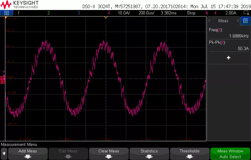
Figure 9. Phase current waveform when the air inlet is blocked
5 Conclusion
MM32SPIN25PF is a high-performance motor drive chip launched by Lingdong Microelectronics. Its main frequency up to 96MHz and 32- bit hardware divider can meet the high-speed computing requirements of the sensorless magnetic field-oriented (FOC) sine wave algorithm . Its built-in comparator and operational amplifier greatly simplify the design of the motor driver board and reduce the BOM cost of the entire solution.
All reference designs on this site are sourced from major semiconductor manufacturers or collected online for learning and research. The copyright belongs to the semiconductor manufacturer or the original author. If you believe that the reference design of this site infringes upon your relevant rights and interests, please send us a rights notice. As a neutral platform service provider, we will take measures to delete the relevant content in accordance with relevant laws after receiving the relevant notice from the rights holder. Please send relevant notifications to email: bbs_service@eeworld.com.cn.
It is your responsibility to test the circuit yourself and determine its suitability for you. EEWorld will not be liable for direct, indirect, special, incidental, consequential or punitive damages arising from any cause or anything connected to any reference design used.
Supported by EEWorld Datasheet
EEWorld
subscription
account

EEWorld
service
account

Automotive
development
community

Robot
development
community

About Us Customer Service Contact Information Datasheet Sitemap LatestNews


Room 1530, 15th Floor, Building B,
No.18 Zhongguancun Street,
Haidian District,
Beijing, Postal Code: 100190
China
Telephone: 008610 8235 0740
 京公网安备 11010802033920号

 EH15010Q


