Program features:
ARM Cortex-M0 high-performance motor driver chip
32K bytes of flash memory, 4K bytes of memory, 72MHz high-speed operation , and built-in divider, ADC , comparator ... etc.
120/150 degree sensorless square wave drive
Motor speed up to 100,000rpm (2-pole motor)
Speed command input can be analog voltage or PWM signal
FG output
Constant speed or constant power operation
Complete protection mechanism: overcurrent protection, stall protection, overvoltage/undervoltage protection
Water pump exclusive features :
When no-load, high speed generates large suction force to lift water up.
When loaded , high torque is used to meet the requirements of the measuring range.
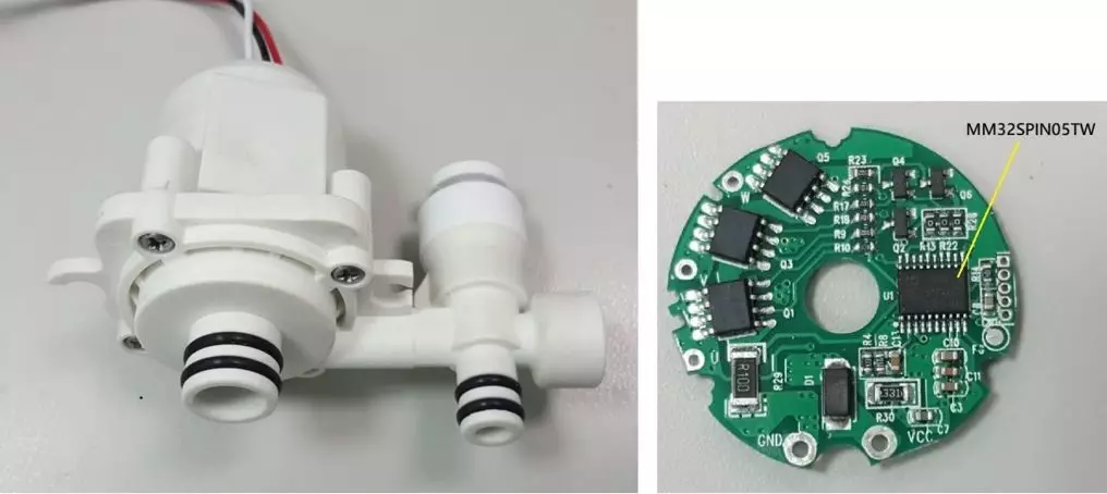
Figure 1. Left : Common 24V/1 3 W small water pump;
Right picture : Driver board using MM32SPIN05TW
2. Principle of sensorless square wave driving technology
Here we introduce the technical principles and implementation methods of sensorless square wave drive.
Correspondence between phase voltage and Hall signal
Square wave drive with sensor (Hall component), the MCU can obtain the position of the rotor through changes in the Hall signal for correct phase commutation. How to obtain the position of the rotor when there is no Hall component? Observe the square wave driving waveform with Hall component in the figure below. The commutation points are all located when the Hall state changes, as shown by the blue dotted line. At the same time, it can also be found that while the Hall state remains unchanged, there must be a The phase is "undriven" and rotates inertly and assumes dynamo status, as shown by the red indicator. This "undriven" period is extremely useful, and we will use its voltage changes to replace the function of the Hall component.
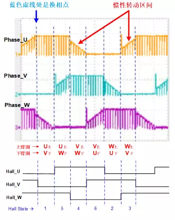
Figure 2. Correspondence between phase voltage and Hall signal
Zero-crossing detection replaces Hall signal
This section will teach you how to use the voltage change in this "undriven" inertial rotation area to replace the function of the Hall component. Please refer to the figure below. First, we define the "Zero-crossing Point", as shown in red The origin of the name "zero-crossing point" is that this point is located in the center of the "undriven" period of a certain phase. The phase current is 30 degrees before it (before commutation) and 30 degrees after it (after commutation). ) is the opposite direction. Therefore, if the position of this point can be detected, the next commutation point will be delayed by another 30 degrees, thus replacing the function of the Hall component!
Observe the figure below again. The phase voltage at the zero-crossing point (when the PWM signal is High) is approximately 1/2 of the DC_bus. We can use the ADC sampling function of the MCU to perform this detection work. The details will be explained in the next section. Implementation method. Note: The concave or convex phase voltage changes in the U-shaped black box in the figure below are caused by the current changes at the commutation moment acting on the windings of the motor (V=L*di/dt). It must be Zero-crossing detection can be performed only after avoiding it.
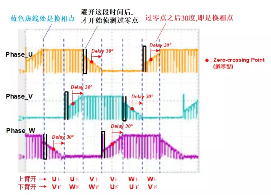
Figure 3. Zero-crossing detection replaces Hall signal
How to implement zero-crossing detection
Before using the MCU's ADC to detect the zero-crossing point, the phase voltage must be divided first and then low-pass filtered to obtain a DC voltage with a level lower than 5V. The threshold for determining the zero-crossing point is set to the DC voltage amplitude. 1/2 of the value. As the motor speed and load are different, the amplitude of the DC voltage will change. Therefore, the threshold of the zero-crossing point is also adjusted, which can be sampled and calculated by the MCU in real time. The schematic diagram is as follows :

Figure 4. Implementation of zero-crossing detection
3.Hardware design
The reference schematic diagram of the motor driver board based on the sensorless square wave drive for " small water pump " based on MM32SPIN05TW is as follows:
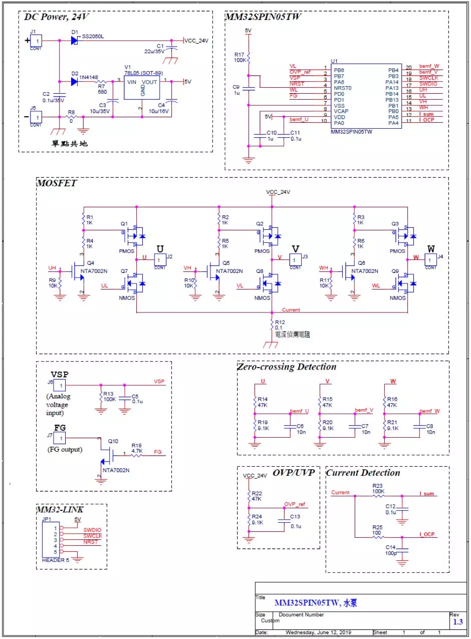
Figure 5. Small and medium power water pump based on MM32SPIN05
Motor drive board schematic diagram
4.Voltage waveform
This application case uses a 120-degree square wave drive. The phase voltage waveforms at no-load and with load are as follows: ( the speed is 12000rpm and 5500rpm respectively)
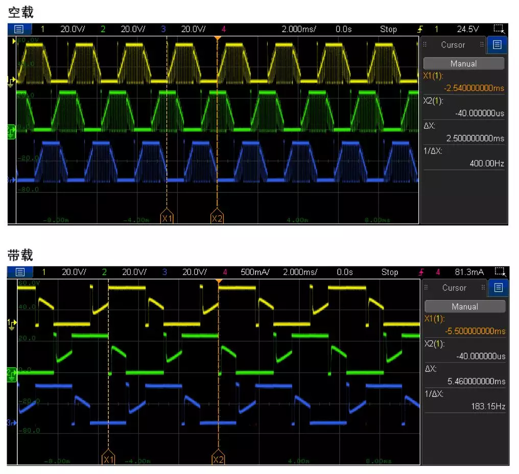
Figure 6. Phase voltage waveforms at no-load and loaded conditions
5 Conclusion
The MM32SPIN05 series is a basic high-performance motor drive dedicated chip launched by Lingdong Microelectronics , which can meet the needs of most square wave/sine wave algorithms.
All reference designs on this site are sourced from major semiconductor manufacturers or collected online for learning and research. The copyright belongs to the semiconductor manufacturer or the original author. If you believe that the reference design of this site infringes upon your relevant rights and interests, please send us a rights notice. As a neutral platform service provider, we will take measures to delete the relevant content in accordance with relevant laws after receiving the relevant notice from the rights holder. Please send relevant notifications to email: bbs_service@eeworld.com.cn.
It is your responsibility to test the circuit yourself and determine its suitability for you. EEWorld will not be liable for direct, indirect, special, incidental, consequential or punitive damages arising from any cause or anything connected to any reference design used.
Supported by EEWorld Datasheet
EEWorld
subscription
account

EEWorld
service
account

Automotive
development
community

Robot
development
community

About Us Customer Service Contact Information Datasheet Sitemap LatestNews


Room 1530, 15th Floor, Building B,
No.18 Zhongguancun Street,
Haidian District,
Beijing, Postal Code: 100190
China
Telephone: 008610 8235 0740
 京公网安备 11010802033920号

 DG302C/D


