This time I heard that Lichuang was going to hold another winter vacation training camp. I signed up with great joy. The last Tuya training camp was put on hold because I had to participate in the Hunan Provincial Skills Competition. It was really a pity. Fortunately, it was during the competition. Won first prize.
By studying the Tuya IoT module, I feel that it is different from the EMW3080 (Alibaba Cloud Feiyan) from our previous summer training camp. EMW3080 writes triples, and MUC then operates the IoT module through AT commands. This time Tuya WB3S IoT module has two modes; the first is development-free, which is easy to understand, that is, you don’t need to write the code yourself, you can use it as soon as you get it. This project can be used for graduation projects, and the cost is less than 100 yuan. It is really cost-effective.

The picture above shows Qingke EMW3080 Alibaba Cloud Feiyan IoT module

The picture above shows Tuya WB3S IoT module
I have been thinking about why I don’t need to write code. It turns out that the required functions have been submitted during the lot platform configuration, and the firmware has been burned when shipped. The second mode is low-code MUC development: by transplanting the SDK to control the IoT module to complete some advanced operations, although it is low-code, it is still difficult for a novice like me (low-key), Tuya Internet of Things itself It communicates with the MCU through a specific protocol to obtain the current ambient temperature, humidity and other information, and then uploads it to the cloud so that it can be viewed on the mobile phone. I will introduce the Tuya IoT module here. For more information, please watch Lichuang Bilibili video.
https://www.bilibili.com/video/BV1S54y167v1
It is recommended to take a look at the excellent works of the previous issue: https://oshwhub.com/recommend/tuya_camp
For multi-functional sensors , there is no development-free solution on the Tuya lot platform. The temperature and humidity module with a single function is a bit insufficient for us. I still want to add a carbon monoxide sensor and a smoke sensor, and pass the warning of the Tuya IoT module. Reminder, you can receive information anytime and anywhere on your mobile phone. This feature is very good and greatly improves security.
When we make a home monitor, we must first consider the effect and mobility of the product. Unlike the small lights and fans we make, the home monitor, as the name suggests, should be kept at home to monitor the quality of the air, so we must be careful in terms of product effectiveness. The first time you know that an alarm occurs, you have to use a buzzer, and one is not enough.
As for the sensor , I used a CO sensor, which is a carbon monoxide sensor. It is very helpful for people who burn coal at home in winter. You may not think you need it, but your elderly family members definitely need it. I also added a smoke sensor, which is useful when we leave the house. At all times, the smoke status in your home is monitored at all times. If a fire breaks out, it will be uploaded to the cloud as soon as possible, and the cloud will then push it to the mobile phone to nip it in the bud. For temperature and humidity, I still use the module used in the training camp. Although it is not easy to solder, it is the same as the BGA chip. I can’t laugh or cry. I will use it if others use it. After all, it is an official designated product. Sound and light alarm, as the name suggests, sound and light prompt together to prevent false triggering. I used two buzzers and two LEDs. Since the PCB area is limited, I used a 0805 package.
Let me mention here, when I first started learning drawing board, I liked to use 1206 package because it is easy to solder. When there are too many components in the back, 1206 cannot fit in. My teacher likes to use 0603, which I can’t even see clearly. I will stick to 0805. . When you first start learning drawing board, you do whatever you like. You don't necessarily have to follow other people's instructions. Experience is accumulated slowly.
For microcontrollers , I suggest that friends who are just getting started should use STC. It is simple and easy to understand. This time I originally used STC15W4K56S4 (don’t ask why not STM32, when writing this article, it is already 6 US dollars per piece). Later When I checked the relevant information on the Internet of Things, I found that Lingyao also has a temperature and humidity IoT module. It uses STC8A8K. I didn't know the reason at first, but I found out later when I saw that there was no IIC. It happened to be STC8A8K during Tuya's live broadcast. As long as the ADC is sufficient, the sensor and battery voltages need to be collected. Of course, a 2.5V reference voltage source must be added. It is okay if it is not added. Directly connecting the power supplied by the MCU may not be accurate, but it can be used if the accuracy requirements are not high. Another random problem is that if a resistor voltage divider is used to collect the battery voltage, the battery will have a certain leakage current. This is also a problem and deserves our in-depth exploration.
Then for the power supply , we can convert the mains power to 5V to power the entire module. There was a mini DC power supply in the summer training camp that was very easy to use. I planned to use this at first, but later I found that a power outage was a big problem. So I used lithium battery for power supply. The problem caused by lithium battery power supply is how to charge it. Plugging and unplugging is very troublesome. Isn't that troublesome? So I used wireless power supply. I have studied wireless charging before and I am familiar with it. If you want to take a closer look at the wireless charging solution, you can check out the detailed analysis of the hardware later.
The power supply part is the most difficult problem in my entire device. Since the voltage of our lithium battery is only 4.2V when fully charged, we have to consider the voltage drop of the LDO and the voltage drop of the entire power supply. This time I will present the best solution to everyone. At the same time, I would like to thank Mo Gong for his guidance on the wiring of my power supply. It took two days to draw the schematics one after another. I hope you can read it carefully
Regarding the hardware and software parts of the entire project, I will introduce it to you carefully and make up for the weak students. If there is anything wrong with what I said, please leave a message below. If you think I said it well, please help me. Thumbs up!
The story begins a month ago. Coal stoves are often used in rural areas in winter. My mother is over fifty years old and her movements have begun to slow down. I am the only son and the youngest in the family. That night, my mother put the coal stove in the room where the TV was to dry clothes, and then went back to the bedroom to sleep. However, she didn't expect that the door was not closed tightly, and all the carbon monoxide poured into the bedroom. The next morning, my mother fell to the ground as soon as she arrived. Fortunately, the neighbors in the village noticed something was wrong, broke open the door of my house, and sent my mother to the hospital in the town. I was studying in Changsha, and my mother was the only one at home. My third sister rushed home from Guangzhou overnight after hearing that my mother had fallen ill. Fortunately, it was discovered early, and my mother almost recovered after being admitted to the hospital for a few days.
Afterwards, I asked my mother why she didn't pay attention. She smiled and said, "As I get older, I am no longer useful. Fortunately, it's okay this time, otherwise you guys would have rushed back to play gongs and drums." I didn't dare to open WeChat to read messages in those days, for fear of seeing my mother falling ill. Yes, she accompanied me through junior high school and high school. After college, she rarely went home. In the blink of an eye, my mother became what children call an old woman. I have never forgotten that my mother asked me if the tuition would be very expensive when she heard that I was admitted. Yes, I should work harder and not let down my mother's love for me.
I have always wanted to develop some fun, good-looking, and novel products, but I never thought of developing one for my family that they can use. I took advantage of this training camp organized by Lichuang and Tuya to make a carbon monoxide and smoke monitor. , simple, but an important love. Looking at my mother busy in the kitchen, I feel warm in my heart. I hope I can always taste my mother's cooking, so I will make a smart home monitor for my mother!
Smart home monitor trailer https://www.bilibili.com/video/BV1X5411E78o/
1. 触摸按键模块

触摸按键就是通过触摸金属片从而控制开断,这个触摸芯片的型号为RH6015,在立创商城上卖的非常便宜,输入电压5V和3.3V都可以选择,4脚和6脚为触发模式选择,我们可以查阅数据手册来进行设置。
2. TTL下载电路

TTL下载电路这边很简单,为CH340C数据手册上典型的电路,这里要注意的是V3引脚,在使用5V供电时要接退藕电容到地,还有就是TXD引脚,要接一个二极管或者电阻防止反向供电导致下载出现问题。
3. USB供电电路

当插上USB供电这部分我做了两路供电,第一路是ME6215 LDO,将5V转为3.3V为MCU供电,但是MCU下载时需要掉电,所以我又增加了AMS1117为CH340供电,我在ME6215的CE引脚上接了一个开关来控制芯片的使能从而控制下载电路。
4. 无线充电接收电路

无线充电这部分简单,但是也有讲究,准确来说这个是无线充电的接收端,四个二极管进行全桥整流,但是必须要用快恢复二极管(无线电能传输为高频电流),由于整流出来的电压较高,需要使用大电压的电容滤波,LOD也要选择大电压输入的。排针上就是插一条绕起的杜邦线,就是简单的无线充电接收线圈。
5. 温湿度传感器电路

温度传感器为SHT30,涂鸦官网推荐,数据接口为IIC,在电源端要加100nF退藕电容,防止电源噪声引起数据偏差。
6. 锂电池充电及供电电路

锂电池充电模块为经典的TP4056,这款芯片的3脚和2脚为充电电流设置,R20为1.2K时,电流达到最大1A。锂电池为整个电路供电部分采用的是ME6215,为什么用这个芯片呢,为什么不用AMS1117,因为AMS1117的压降较ME6215较大,锂电池充满电为4.2V,每1V的电压都非常宝贵,所以得采用压降较小的ME6215。在切换电池和USB供电的电路,我采用了P沟道的Mos管来切换,当未插入外接电源时,mos管g脚电压为低,mos管导通,当接入外接电源时,mos管的Vgs为关断电压,可以快速的在5V和内置的锂电池之间切换。由于mos导通压降非常的小(Rdson)所以不会过多的消耗锂电池的电量。
7. 电池电压采样电路

电池的电压需要我们去检测,检测有复杂的方法,也有简单的方法,简单的方法就是通过两个电阻分压,把4.2V分成2.1V给单片机采集,但是在电阻上长期以往会有一个漏电流,所以我采用了一个P沟道MOS管来开启电池和电阻之间的通断,以达到减少漏电流的作用。
8. MCU最小系统

单片机采用的是STC的8A8K系列,本来打算用15W4K64,但是由于15系列没有IIC接口,只有模拟IIC,所以我采用了官方推荐的STC8A8K,正好在物联网零妖的博客上有8A8K采集温度上传物联网的项目,而且8A8K的价格也很便宜。使用这个单片机注意的方面第一个是AVCC脚,就算你不用AVCC脚,也要接电源,第二个,在ADC输入需要滤波电容,最好用NP0电容。第三个是RXD和TXD,我们最好使用两个电阻,方便我们调试,防止串口出现问题我们无法进行修改和下载程序。
STC8系列单片机是不需要外部晶振和外部复位的单片机,是目前全球最快的8051 单片机(相同时钟频率),比传统的8051约快12倍(速度快11.2~13.2倍),依次按顺序执行完全部的111条指令,STC8系列单片机仅需147个时钟,而传统8051则需要1944 个时钟。STC8 系列单片机是STC生产的单时钟/机器周期(1T)的单片机,是宽电压/高速/高可靠/低功耗/强抗静电/较强抗干扰的新一代8051单片机,超级加密。指令代码完全兼容传统8051。
MCU内部集成高精度R/C时钟(+0.3%,常温下+25°C),-1.8%—+0.8%温飘(- 40°C—+85°C) ,-1.0%—+0.5%温飘(-20°C—+65°C)。ISP编程时5MHz~ 30MHz宽范围可设置,可彻底省掉外部昂贵的晶振和外部复位电路(内部已集成高可靠复位电路,ISP 编程时4级复位门槛电压可选)。
MCU内部有3个可选时钟源:内部24MHz高精度IRC时钟(可适当调高或调低)、内部32KHz的低速IRC、外部4M~33M晶振或外部时钟信号。用户代码中可自由选择时钟源,时钟源选定后可再经过8-bit的分频器分频后再将时钟信号提供给CPU和各个外设(如定时器、串口、SPI等)。
超高速8051内核(1T), 是全球最快的8051, 比传统8051约快12倍
指令代码完全兼容传统8051
22个中断源,4级中断优先级
支持在线仿真
2.0V~5.5V
内建LDO
-40°C~85°C
最大64K字节FLASH空间,用于存储用户代码
支持用户配置EEPROM大小,512字节单页擦除,擦写次数可达10万次以上
支持在系统编程方式(ISP) 更新用户应用程序,无需专用编程器
支持单芯片仿真,无需专用仿真器,理论断点个数无限制
128字节内部直接访问RAM(DATA)
128字节内部间接访问RAM(IDATA)
8192字节内部扩展RAM(内部XDATA)
外部最大可扩展64K字节RAM(外部XDATA)
内部24MHz高精度IRC (ISP编程时可进行上下调整)
申误差士0.3% (常温下25°C)
-1.8%~+0.8%温漂( 全温度范围,-40°C~85"C)
-1.0%~+0.5%温漂( 温度范围,-20°C~65°C )
内部32KHz低速IRC (误差较大)
外部晶振(4MHz~33MHz)和外部时钟
用户可自由选择上面的3种时钟源
硬件复位
上电复位
复位脚复位(高电平复位),出厂时P5.4默认为I0口,ISP下载时可将P5.4管脚设置为复位脚
看门狗溢出复位
申低压检测复位,提供4级低压检测电压: 2.2V、 2.4V、 V2.7、 V3.0
软件复位
软件方式写复位触发寄存器
Provides 22 interrupt sources: INT0, INT1, INT2, INT3, INT4, timer 0, timer 1, timer 2, timer 3, timer 4, serial port 1, serial port 2, serial port 3, serial port 4, ADC module Digital conversion, LVD low voltage detection, SPI, IC, comparator, PCA/CCP/PWM, enhanced PWM, enhanced PWM abnormality detection
provide 4 levels of interrupt priority
Five 16-bit timers: timer 0, timer 1, timer 2, timer 3, timer 4, among which mode 3 of timer 0 has (unmaskable interrupt) function, timer 0 and timer 1 Mode 0 is 16-bit auto-reload mode with
4 high-speed serial ports: serial port 1, serial port 2, serial port 3, and serial port 4. The fastest baud rate clock source can be FOSC/4.
4 sets of 16-bit PCA modules: CCP0, CCP1, CCP2 , CCP3, can be used for capture, high-speed pulse output, and 6/7/8/10-bit PWM output.
8 groups of 15-bit enhanced PWM can realize control signals with dead zones and support external abnormality detection functions. In addition, there are 4 sets of traditional
PCA/CCP/PWM can be used as PWM
SPI: Support host mode and slave mode and host-slave automatic switching
I2C supports host mode and slave mode
ADC, supports 12-bit precision 15-channel analog-to-digital conversion, the fastest speed can reach 800K (that is, 800,000 analog-to-digital conversions per second)
comparator, a group of comparators nearby
Up to 59 GPIOs: P0.0~P0.7, P1.0~P1.7, P2.0~P2.7, P3.0~P3.7, P4.0~P4.4, P5.0 ~P5.5, P6.0~P6.7, P7.0 ~P7.7
all GPIOs support the following 4 modes: quasi-bidirectional port mode, strong push-pull output mode, open-drain output mode, high-impedance input mode
9. ADC reference voltage power supply

The ADC's reference voltage uses a TL431 voltage regulator chip, and magnetic beads and filter capacitors are added to the input end of the power supply to resist interference. In an environment where the requirements are not very accurate, we can directly connect VREF to VCC, but VCC may fluctuate by about 100mV, which will cause a huge error in accurate analog measurement . This is why I use the TL431 voltage regulator chip here
10. Sound and light alarm circuit

The alarm circuit is very simple. It uses a triode to control the buzzer and uses two buzzers in parallel to increase the loudness.
11. IoT module
 The IoT module uses Tuya Smart WB3S. The important thing to note when using this module is that pin 3 is the enable terminal. It has been pulled high internally. We can connect the resistor to 3.3V.
The following are the parameters of Tuya IoT module


The picture above shows that the price of carbon monoxide and liquefied gas sensors is about 8 yuan each, which is very cost-effective.
12. PCB design considerations

In terms of PCB wiring, first of all, my circuit board has many power chips, so we need to conduct single-point grounding to improve the safety of our power supply system. Secondly, 5V and 3.3V should be circled outward as much as possible, which not only improves wiring efficiency, but also reduces the difficulty of maintenance. The sensor interface should be kept as far away from the power chip as possible to prevent the noise from the power chip from interfering with the accuracy of sensor data collection. The most important point is not to apply copper under the WiFi chip to prevent WiFi signals from being absorbed by the ground. The buttons and LED are placed on the front, and the other main parts are placed on the back. The battery uses 18650 3.7V.
These are the precautions for the entire hardware. I will share with you the problems encountered during the debugging process.
13. Things to note when soldering PCB


In terms of programming, the first thing to consider is the sensor. The sensor I bought outputs analog and digital values at the same time, so we need to use the ADC sampling of the microcontroller, and the ADC sampling needs to be corrected step by step.
#include "stc8.h"
#include "lcd1602.h"
#include "intrins.h" //ADC 特殊功能寄存器
sfr ADC_CONTR = 0xbc;
#define ADC_POWER 0x80
#define ADC_START 0x40
#define ADC_FLAG 0x20
#define ADC_RESFMT 0x20
sfr ADC_RES = 0xbd;
sfr ADC_RESL = 0xbe;
sfr ADCCFG = 0xde;
sfr P1M0 = 0x92;
sfr P1M1 = 0x91;
sbit BEEP = P3^4;
sbit LED = P3^5;
unsigned char Vo; //A/D转换后换算的电压值
void main() { LCD_Init(); //LCD初始化
P1M0 = 0X02;//配置P1.2口为ADC检测输入
P1M1 = 0X01;
while(1) { GetADCResult(0); //获取ADC值 LCD_Manifest(2,11,Vo/10);//显示十位 LCD_Manifest(2,12,Vo%10);//显示个位 if(Vo<15) {BEEP=1;LED=1;} else {BEEP=0;LED=0;} } }
/*---------------------------- Get ADC result ----------------------------*/
unsigned char GetADCResult(unsigned char ch)//这里如有不懂 请仔细看资料
{ //选择P1口的哪一口 这里的口和ch要对应才能达到选择该口
ADC_CONTR = ADC_POWER | ADC_START | ch ;//启动adc电源,开始A/D转换 ,配置采集口 //这么用语句的主要原因就是不能位寻址 //通道选择在后3位所以直接用一个整数表示ch //例如ch=6 那么对应的后三位就是110
_nop_(); //Must wait before inquiry
_nop_(); //设置ADC_CONTR寄存器后需加4个CPU时钟周期的延时,才能保证值被写入ADC_CONTR寄存器
_nop_(); _nop_();
while (!(ADC_CONTR & ADC_FLAG));//Wait complete flag 等待转化完成 ADC_CONTR &= ~ADC_FLAG; //Close ADC 将标志位清零等待下次硬件置1 //也可以写成 ADC_CONTR= ADC_CONTR & ( ~ADC_FLAG) //只读取8位ADC采集结果 并 以2.5v为基准进行换算 Vo=ADC_RES/2.5;//Return ADC result(为显示整数,这里将电压值计算为百分比) return Vo; }
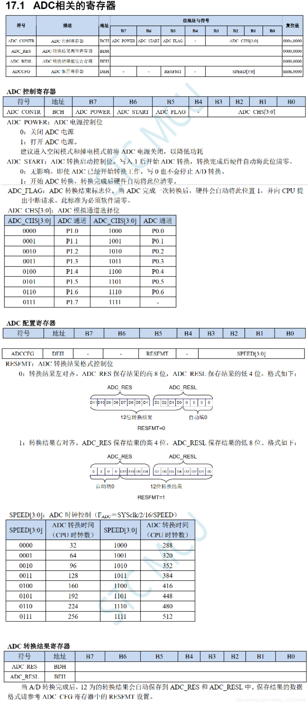
The following is the description of the ADC related registers in the STC8A data sheet:

The picture above shows the program framework
The picture below shows the Tuya lot platform debugging settings.

Added carbon monoxide concentration and smoke concentration alarms

Download the SDK file and compile the file into our main function. Please see the Tuya official website for specific operations.
Bilibili official website video: https://www.bilibili.com/video/BV1pb41117Nt
Regarding transplanting the SDK, we only need to match the functions we use one by one. The information will be automatically uploaded to Tuya WB3S through the serial port, and the IoT module will upload the data to our cloud. Realize every function of our products.

I will upload the program to the attachment for your reference. Most of the programs are completed through transplantation.
After debugging the program, we need to download an APP on the mobile phone to configure the network. Due to space reasons, I will not elaborate on the specific method. It depends on the IoT module you choose.
After several days of joint debugging of software and hardware, we finally implemented the function. An ideal home smart monitor is realized.
For alarm prompts, we can purchase SMS packages or phone packages, so that we don’t need to check the data all the time, which is safe and convenient.
 Although text messages are charged, it is still worth purchasing for safety reasons.
The test video will be placed in the attachment


Let me tell you about the difficulties and ideas encountered in the design process of this project. The first thing is to adjust the sensor sensitivity. It will not work if it is too high or too low. Secondly, on the casing, because the gas needs to flow in before it can be sensed by the sensor, I made holes in the panel. On the keys, the two buttons on the left are springs, and the right buttons are ordinary buttons. In terms of button feel, ordinary buttons seem to be a little worse, but in terms of circuit structure, they must be adopted. Another is that I have done enough homework on battery switching. You can go to Bilibili to watch Mr. Tang’s lecture on electric competition, which introduces this kind of circuit. My wireless charging was also implemented step by step according to his guidance. Although wireless charging Charging has been done a long time ago, and it is very good to use it on the monitor this time, which is convenient and saves trouble. This project took half a month, including two days of circuit drawing, one day of PCB drawing, and more than ten days of welding and debugging. Although it seems simple, it covers a lot of electronic knowledge and I consulted a lot of information, such as the need for filtering when collecting power supply in ADC, etc., which means I have benefited a lot.
Finally, I would like to thank Lichuang and Tuya Smart for bringing me a technical progress and growing myself in the production. I hope I will have the opportunity to participate again in the future!
The tree wants to be quiet but the wind doesn't stop, the child wants to be raised but the relatives don't wait for it. I am here to wish all my friends good health and family happiness in 2021, and go home often when you have time!

All reference designs on this site are sourced from major semiconductor manufacturers or collected online for learning and research. The copyright belongs to the semiconductor manufacturer or the original author. If you believe that the reference design of this site infringes upon your relevant rights and interests, please send us a rights notice. As a neutral platform service provider, we will take measures to delete the relevant content in accordance with relevant laws after receiving the relevant notice from the rights holder. Please send relevant notifications to email: bbs_service@eeworld.com.cn.
It is your responsibility to test the circuit yourself and determine its suitability for you. EEWorld will not be liable for direct, indirect, special, incidental, consequential or punitive damages arising from any cause or anything connected to any reference design used.
Supported by EEWorld Datasheet
EEWorld
subscription
account

EEWorld
service
account

Automotive
development
community

Robot
development
community

About Us Customer Service Contact Information Datasheet Sitemap LatestNews


Room 1530, 15th Floor, Building B,
No.18 Zhongguancun Street,
Haidian District,
Beijing, Postal Code: 100190
China
Telephone: 008610 8235 0740
 京公网安备 11010802033920号

 DL-5338-1490-XTAS


