Infrared thermal imaging camera is used to display circuit board temperature imaging, equipment temperature imaging, etc.
When working, you may encounter the following scenarios:
1. After the newly welded board is powered on, it is found that the current is abnormal. You need to check where the heat on the board is abnormal.
2. It is necessary to monitor the temperature of a certain device (such as a transistor, MOS) to prevent it from overheating and burning.
3. Measure the temperature rise.
Therefore, I need an infrared thermal imaging camera, but I looked online and it costs around 2,000. Although the resolution is very high, I don’t need such good performance, so I just made one myself. The infrared pixels of the AMG8833 are 8x8, which felt too low, so I chose the MLX90640 with 32x24 pixels. The price on Taobao is 172 yuan. Together with the microcontroller and LCD screen, it can be done within 300 yuan.
What it looks like when finished:

Has the following functions:
1. Powered by lithium battery and charged by USB port.
2. Built-in 16M SPI flash, the size of an infrared picture is 150K, so 109 pictures can be saved.
3. SPI Flash is used as a virtual U disk. You can directly view and copy the saved pictures by connecting it to the computer through the USB port.


First public release, completely original.
GPL3.0 open source license.
The overall schematic diagram is as follows:

1. Power supply part

When the USB port is not connected, it is powered by lithium battery. When the USB port is connected, it is powered by USB and charges the lithium battery through TP4057.
2. Screen and SPI Flash

The screen uses a 3.5-inch, 320x240 resolution. SPI Flash uses XT25F128B from Xintianxia, 16MB.
3. MLX90640 and AD buttons.

MLX90640 uses analog IIC driver, and uses ADC to read 3 buttons because the IO port is used up.
4. MCU

The microcontroller uses GD32F103C8T6.
6. Shell selection

The shell is ready-made on Taobao.

There is still plenty of space.
7. PCB


1. Software processing block diagram

2. Transplant the MLX90640 official API library
Get the official API library from github: https://github.com/melexis/mlx90640-library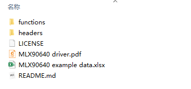
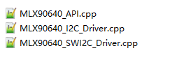
Modify the IIC driver in the API library to your own to complete the transplant.
3. Image interpolation
You can read 32x24 infrared pixels by calling the function in the API library. However, the screen is 320x240, so the original image needs to be interpolated and enlarged and displayed on the screen.
Since the computing power of GD32 is not very strong, a bilinear interpolation algorithm with a relatively small amount of calculation was chosen.
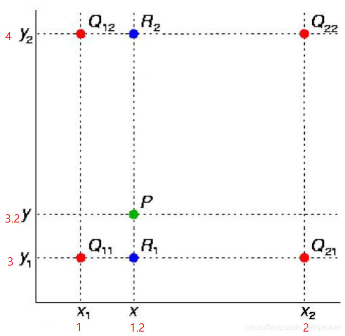
Perform two linear interpolation calculations in the X direction
Then perform an interpolation calculation in the Y direction: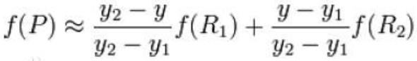
Image effect after interpolation:

4. Convert temperature value to color
Now the 32x24 pixels are enlarged 10 times to get 320x240 pixels, but these pixels still have temperature values of -40 degrees to 300 degrees. How to convert them into color for display?
In fact, there are already conversion specifications, and there are many solutions:
Method of converting temperature to color:
first assume the upper and lower limits of the temperature range and convert the actual temperature data into a value between 0 and 255
Use the converted value to substitute into the following pseudo-color coding calculation function to generate pseudo-color
Check out other color conversion methods on my blog: https://blog.csdn.net/qlexcel/article/details/119421679 .
5. Transplant the Fatfs file system and GD32 USB program
Just match the file system driver read and write functions with the USB read and write functions.


All reference designs on this site are sourced from major semiconductor manufacturers or collected online for learning and research. The copyright belongs to the semiconductor manufacturer or the original author. If you believe that the reference design of this site infringes upon your relevant rights and interests, please send us a rights notice. As a neutral platform service provider, we will take measures to delete the relevant content in accordance with relevant laws after receiving the relevant notice from the rights holder. Please send relevant notifications to email: bbs_service@eeworld.com.cn.
It is your responsibility to test the circuit yourself and determine its suitability for you. EEWorld will not be liable for direct, indirect, special, incidental, consequential or punitive damages arising from any cause or anything connected to any reference design used.
Supported by EEWorld Datasheet
EEWorld
subscription
account

EEWorld
service
account

Automotive
development
community

Robot
development
community

About Us Customer Service Contact Information Datasheet Sitemap LatestNews


Room 1530, 15th Floor, Building B,
No.18 Zhongguancun Street,
Haidian District,
Beijing, Postal Code: 100190
China
Telephone: 008610 8235 0740
 京公网安备 11010802033920号

 C7S-80.000-16-1530-3-R


