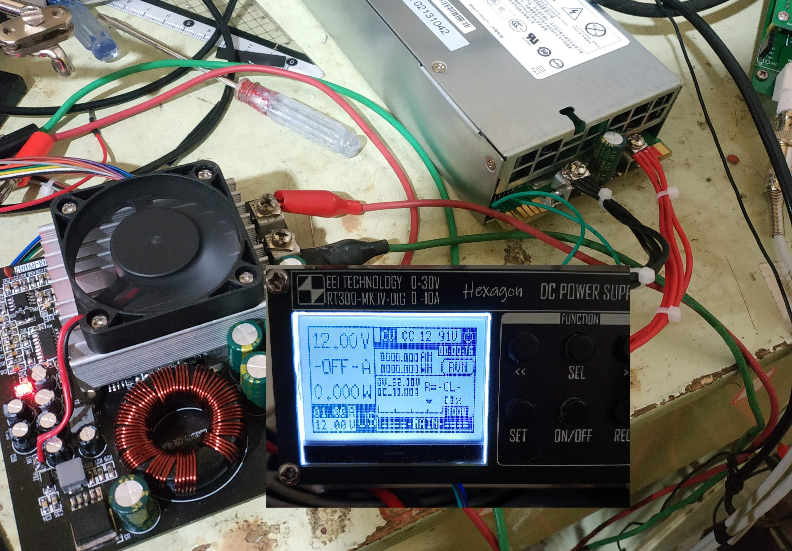
EEI TECHNOLOGY RT300Series MK.IV-DIG EEI TECHNOLOGY RT300-MK.IV project coupled inductor SEPIC numerically controlled step-up and step-down DC adjustable power supply module has constant voltage, constant current functions, custom overvoltage (OVP), overcurrent (OCP), Over-power (OPP) protection, software self-calibration algorithm makes the output voltage and current less than the set value less than 0.01, no blocking delay is used in the program, and a Σ-Δ ADC is used, while the data is refreshed quickly, the data is also basically It won't vibrate. Data storage function: Built-in 11 groups of data storage space, each group can store the set voltage and current (one group is reserved to store the data set before power failure). In the setting interface, you can choose the array of power-on memory (USER or M0 -M9), USER is the data saved before power off. Step setting: Use the two buttons "<<" ">>" to switch the X1 X0.1 X0.01 step, and turn the encoder to adjust. Input range: 11-30V Output range: 0-30V, 0.01 step 0-10A0.01 step (automatic limit 8A when output above 20V) Output power (maximum value) 240W, maximum input current stress in the full input range: 28A Converter Efficiency: Boost: 85-90% Buck 82-85% Setting-acquisition error: ±0.005 Voltage acquisition error: ±0.02 (maximum value) Current acquisition error: ±0.02 (maximum value) Output ripple: depending on the output voltage It depends on the current (12V input, output 30V 5A, the measured ripple is about 70mvpp) At the beginning of the project, the output diode overshoot occurred, and when the output was turned on after powering on, the output voltage overshoot occurred due to excessive overshoot. The problem, as well as some problems with the current loop, have now been resolved. In addition, because the coupling capacitor uses MLCC, when the PWM is discontinuous (such as short circuit triggering constant current), there will be a little howling. Version iteration notice!!!!!!!!!! [RT300-MKV-EXTREME] has a wider output range (0-50V). The maximum input current stress of 30A can ensure that it can run at full 250W within the full input range. 0-10A constant current range, and has the function of intelligently limiting the output current upper limit. Using synchronous rectification pre-boost scheme, it generates less heat, smaller size, and has a maximum efficiency of 97%. The switching frequency is increased to 250K, lower voltage ripple. The charge pump negative voltage solution has lower starting current, which perfectly solves the problem of XL1583 not vibrating under negative pressure. Feedforward voltage mode control, faster dynamic response. The improved feedback loop makes the DC gain close to infinity, thus ensuring good load regulation (< 0.001%). Zero-drift high-side sampling collects the output current, so that the output load can be grounded with the input power supply without affecting the current collection, and the output There won't be any pressure drop at the end. It comes with a diode simulation mode to effectively prevent current backflow at the output end. Self-calibration algorithm V3 speeds up DA calibration and has a memory function, that is, after completing a full-range self-calibration, the calibration data of each point will be automatically memorized. Intelligent fan control dynamically adjusts the fan speed according to the output power. Easier to make, all using common parts, eliminating drilling and other steps. Major update!!! RT300-MKV-EXTREME will use 2.8-inch color screen and traditional black and white screen versions, and the color screen communication protocol is completely open. Those who are capable can make the serial port screen part by themselves. Note: Coupled inductor The inductor of SEPIC is wound using a loose coupling method (magnetic rings are wound in one group on each side). It must not be tightly coupled, otherwise a large ripple current will appear in the coupling loop, and the inductor will seriously heat up. Error amplifier and current sampling The amplifier cannot be used with a low slew rate, otherwise the overshoot will be too large, and the switch tube may be burned when a sudden short circuit triggers the constant current. The screen uses a 1.7-inch 12864 front-display LCD screen from Huijing. The main control is UC1701X, which can also be used. Jin Yichen's 1.7-inch black and white negative display (the program is compatible with the LCD display of ST7565 ST7567 master), but it is not recommended to change the screen. Some screens of unknown origin may be rotated 90 degrees after being installed, and may also be mirrored. Program flashing method: Use the STLINK mass production tool to flash, first burn "RT300-MK.IV_DEBUG.bin", then adjust the system settings and protection settings according to the instructions, and then flash "RT300-MK.IV_LCD. bin” bin file and instruction manual are in the attachment, please download them yourself. Do not use a low-power power supply for testing, otherwise the power supply may not be able to provide enough current to cause the negative voltage part to oscillate, and the power module will not work, which can easily lead to misdiagnosis of faults. It is recommended to use a 12V 5A or above power supply for testing. Note one thing (very important): the input and output capacitors must be of high quality (1000uF ESR < 0.04Ω), otherwise the capacitor may explode due to excessive internal resistance during heavy load (personal experience) Electrolysis Capacitor purchase link: https://item.taobao.com/item.htm?id=522589612404 Heat sink purchase link: https://item.taobao.com/item.htm?id=588885433279 (select length 60MM), please Drill your own holes. LCD screen purchase link: https://item.taobao.com/item.htm?id=523956578037 Recommended power MOS models: 1X IPP034N08 (RdsON: 3.4mΩ Qg: 69nC Vdsmax: 80V) 1X IPP037N08 (RdsON: 3.7mΩ Qg : 88nC Vdsmax : 80V) 1X FDP045N10 ( RdsON : 3.9mΩ Qg : 54nC Vdsmax : 100V) 2X IRFB3607 ( RdsON : 7.3mΩ Qg : 56nC Vdsmax : 75V) It is not recommended to use that kind of ancient tube (such as 75NF75), this kind of tube The gate charge is very large (117nC), which is difficult to drive at high switching frequencies, and its internal resistance is also very large (about 10mΩ). Regarding the winding method of the coupled inductor: it must be wound in a loose coupling method (that is, one on each side of the magnetic ring Winding), do not try to save trouble by splitting two windings of multi-strand inductors, otherwise a large loop current will be generated, causing the inductor and switch tube to heat up violently, and in severe cases, the switch tube will be burned. Winding parameters: Wind 0.7mm x 6 strands on the input side 7 times, wind 0.7mm x 4 strands 7 times on the output side, do not wind more or less. Magnetic ring model: CS130125 outer diameter 33mm, inner diameter 20mm, magnetic permeability 125. As shown in the figure about triggering Constant current, CC CV cursor does not jump problem: Many friends have reported this problem recently. The fault phenomenon is that when the output is short-circuited, the CC CV cursor does not jump, and the cursor is stuck in the CV, making it impossible to complete self-calibration in CC mode. And when the output is released, the voltage is much higher and the self-calibration fails. The reason for the problem is that the U15 or LMV331 material was selected incorrectly. The pin definitions of this material are divided into several types, so everyone chose the wrong material. I used LM331IDBVR (SOT-23-5) , most of the people who have this problem use another kind of LMV331, the suffix is unknown, but the package is SC-70-5 (the appearance is very similar to SOT-23-5, but smaller than the former). If you really can't find this material, it doesn't matter. We can use a SOT-23-5 general-purpose op amp (such as LMV321), and it will still work. Regarding the input fuse: the power module uses a medium-sized car fuse. The purchase link for the holder: https://detail.tmall.com/item.htm?id=593901939774 The price of STM32 has increased significantly recently, and everyone has begun to choose domestic alternative models. Okay, let me explain here: currently it has only been verified that the program can run perfectly on APM32F103C8T6/CBT6 and CKS32F103C8T6/CBT6. GD32 HK32 is not supported for the time being due to major hardware changes. Special note: Due to my poor programming skills, in order to avoid causing controversy, the source code will not be disclosed. Please understand. Update log 10.3 Update: Do not weld C4 and C5. If welded, it will cause large switching loss and affect its efficiency. 10.14 update: Please change R60 R61 to 5.1K 20K to solve the problem that the XL1583 negative voltage part may not work when powered on. 10.16 update: Please add a bleeder resistor to the output capacitor with a resistance of 470R-1K and a power of 3w. 10.31 update: R113 R47 changed to 18K 2K. 11.24 update: The PWM controller was changed to EG3525, the error amplifier U3 was changed to TL082, and the remaining three operational amplifiers were changed to OPA2277 (it is not a big deal to use the original LT1366). 12.8 update: U15 is replaced with LMV321IDBVR, or other SOT-23-5 general-purpose op amps to solve the problem of CC CV not jumping. Material list: (only part of it, please download the attachment for the complete material list) PCB preview PCB back preview system structure diagram Ripple power module measured when inputting 12V and outputting 30V 5A Physical power module + PCB panel main interface 230W stress test Medium Buck Efficiency Curve Boost Efficiency Curve Data Storage Overvoltage, overcurrent, and overpower protection setting interface RT300-MK.IV PACK#2 PCB panel function demonstration video address https://www.bilibili.com/video/BV1v54y1C7Vm /


 京公网安备 11010802033920号

 STS3C3F30L


