Original post address: https://radiokot.ru/circuit/digital/measure/108/
how to use
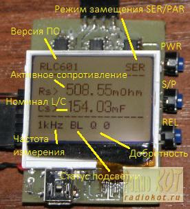
To turn on the device, press and hold the PWR button for 2 seconds. Afterwards, a welcome message will appear on the screen and calibration will begin. In the first step of the calibration, the resistance of the opened probe will be measured, if this is not the case, the device will display the prompt "Open leads", after opening the probe or removing the part from it, the device will start the calibration process. The second step of the calibration is to evaluate the resistance of the probe in the closed state; to start the calibration you need to close the probe first and until complete the prompt "Close Lead" will appear on the screen. After all calibrations are completed, the device immediately switches to measurement mode and displays the measurement results on the screen.
 Control is via three buttons on the side of the board (PWR, S/P, REL). When on, short press the PWR button to turn on/off the backlight. Enabled by default when enabled. Holding the button down for a long time will turn off the device. The S/P button allows you to toggle replacement mode between two modes:
-Serial , when the element under test is represented by an active resistor in series with a capacitor/inductor. The SER icon at the top of the screen indicates this mode on the screen and displays the measured values with the names Rs, Cs, Ls. This is the main mode of the device and allows you to measure the capacitor (ESR) and the internal resistance of the coil simultaneously.
- Parallel substitution mode, when the component under test is represented by an active resistor connected in parallel with a capacitor/inductor. This mode is primarily useful for evaluating components with high internal resistance, such as when you need to estimate the leakage current of a capacitor or the parasitic capacitance of a high-resistance resistor.
The REL button allows you to turn on the relative measurement mode, in which you can subtract the contribution of individual elements to the measurement. Using this mode, you can, for example, measure elements at constant voltage. The device itself does not allow connecting a voltage source to the probe, but if a capacitor in series with the probe is turned on, it is possible to measure, for example, the internal resistance of a battery. In this case, the measurement scheme is as follows - the isolation capacitor must be connected to the probe of the device and measured, then the relative measurement mode must be turned on and the reading on the screen will be reset to zero. . Afterwards, one of the probes must be disconnected from the isolation capacitor and the battery between this probe and the free end of the isolation capacitor must be opened. The device will display the battery's internal resistance.


All reference designs on this site are sourced from major semiconductor manufacturers or collected online for learning and research. The copyright belongs to the semiconductor manufacturer or the original author. If you believe that the reference design of this site infringes upon your relevant rights and interests, please send us a rights notice. As a neutral platform service provider, we will take measures to delete the relevant content in accordance with relevant laws after receiving the relevant notice from the rights holder. Please send relevant notifications to email: bbs_service@eeworld.com.cn.
It is your responsibility to test the circuit yourself and determine its suitability for you. EEWorld will not be liable for direct, indirect, special, incidental, consequential or punitive damages arising from any cause or anything connected to any reference design used.
Supported by EEWorld Datasheet