The T12 white light soldering iron is also a very classic project in electronic DIY, so much so that the T12 white light DIY soldering iron is also a standard tool for enthusiasts and professionals; the entire circuit of T12 can be said to be a standard temperature control system, so this system is slightly modified , you can realize various thermostat solutions;
In this example, we did not use an auxiliary microcontroller to implement it, but concentrated all functions on the six expansion ports E1~E6. Because E5 and E6 can have PWM functions, the entire function does not require an extended microcontroller at all.
Since the thermocouple is a nonlinear sensor, when designing this project, the main system also specially upgraded the corresponding statements for the nonlinear sensor to facilitate quick table lookup to obtain calculated values;
| content | Download link |
|---|---|
| Fool update package | http://shmictrl.com/download/t12_rom.zip |
| Schematic and PCB | https://lceda.cn/zhqsoft/shmictrl-28-t12 |
| sHMIctrl project file | http://shmictrl.com/download/shmictrl-t12.sz |
sHMIctrl has six expansion ports, which can cover input, output, AD, PWM and other ranges. So we found that we can directly use these 6 expansion ports to achieve T12 control without using an auxiliary microcontroller, so we compiled these 6 Port expansion plan:
| port | model | describe |
|---|---|---|
| E1(gpio0) | enter | sleep switch |
| E2(gpio1) | AD | NTC |
| E3(gpio2) | AD | Input voltage, 10:1 voltage divider |
| E4(gpio3) | AD | After the thermocouple is amplified by operation |
| E5(gpio4) | PWM or output | Active or passive buzzer |
| E6(gpio5) | PWM | Soldering iron core heating |
In the first issue, we first implement the basic function of the soldering iron, namely heating control, and sleep, NTC and buzzer will be implemented slowly later.
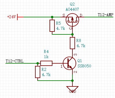
PWM signal controls MOS to heat the soldering iron tip
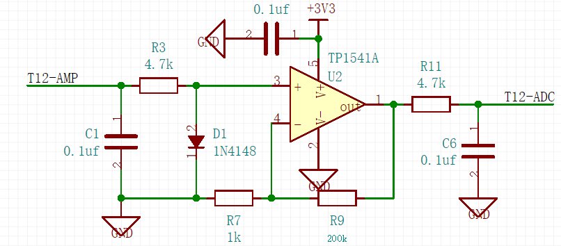
A standard operational amplifier circuit amplifies the signal about 200 times
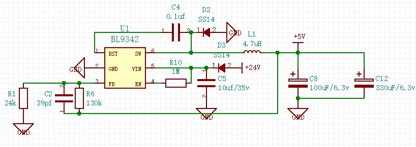
Anything below 40V can be input and converted to 5V for use by the screen and microcontroller. C12 has a reserved pad.
For all schematics, please see: https://lceda.cn/zhqsoft/shmictrl-28-t12
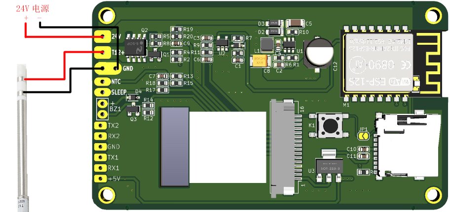
The position of ESP12s is reserved in the picture. In theory, it can be made into an IoT soldering iron, but it has no practical use and is just reserved.

All reference designs on this site are sourced from major semiconductor manufacturers or collected online for learning and research. The copyright belongs to the semiconductor manufacturer or the original author. If you believe that the reference design of this site infringes upon your relevant rights and interests, please send us a rights notice. As a neutral platform service provider, we will take measures to delete the relevant content in accordance with relevant laws after receiving the relevant notice from the rights holder. Please send relevant notifications to email: bbs_service@eeworld.com.cn.
It is your responsibility to test the circuit yourself and determine its suitability for you. EEWorld will not be liable for direct, indirect, special, incidental, consequential or punitive damages arising from any cause or anything connected to any reference design used.
Supported by EEWorld Datasheet
EEWorld
subscription
account

EEWorld
service
account

Automotive
development
community

Robot
development
community

About Us Customer Service Contact Information Datasheet Sitemap LatestNews


Room 1530, 15th Floor, Building B,
No.18 Zhongguancun Street,
Haidian District,
Beijing, Postal Code: 100190
China
Telephone: 008610 8235 0740
 京公网安备 11010802033920号

 PTN0502E1042BGT3


