It is modified based on foreign open source. I won’t tell you where to change it. If you don’t believe it, you can call mine and the foreign open source one back and try to solder them. The following is the foreign open source
https://oshwlab.com/RandomThoughts/stm32-blue- pill-breakout-board
Taobao's C8T6 minimum system can be used after buying it and plugging it in directly.
Power supply selection is difficult
I’ll just bring in the foreign open source ones and see for myself (you’ll know everything by looking at the PCB and schematic diagram)
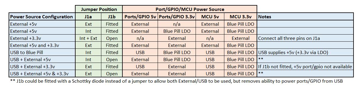
J1a +3.3v Int/Ext Voltage Select - selects whether +3.3v to ports/gpio/power distribution is either powered from the external +3.3v supply or the Blue Pill's onboard LDO (not recommended). Not fitting the jumper isolates +3.3v from the port/gpio/power pins.
J1b MCU +5v selects whether the Blue Pill board is supplied +5v from the external power supply - useful if connecting the USB port to the Blue Pill board in order isolate the external +5v power supply from the USB power supply or 3.3v from JTAG. Also if powering Blue Pill from external +3.3v, allows isolation from +5v so the Blue Pill LDO is not used.
+3.3V supply can be switched between an external +3.3V supply or an internal +3.3v from Blue Pill board (current limited, may damage the STM32 if too much current is drawn from the BLue Pill LDO). If using +3.3v power distribution outputs or multiple and/or power greedy devices from ports then an external +3.3v power source is recommended.
When using USB power and external +5v at the same time leave J1b open - disconnects the MCU 5V line (USB supplied) from the external 5v (external 5V supply used to power ports/GPIO only). Alternatively fit a Schottky Diode instead of the J1b header to allow both PSU to be used.
When using the USB power or external +5v, to power the Blue Pill MCU, and an external 3.3v supply at the same time then do not connect the Blue Pill 3.3V line to the external 3.3v supply (J1a must be set to Ext).
When using the external +3.3v only to power Blue Pill Board (i.e. all three pins on J1a connected) then J1b should be open - disconnects the +5v breakout board rail from the Blue Pill board to prevent any reverse current pull through the Blue Pill LDO if a +5v port/gpio is connected.

All reference designs on this site are sourced from major semiconductor manufacturers or collected online for learning and research. The copyright belongs to the semiconductor manufacturer or the original author. If you believe that the reference design of this site infringes upon your relevant rights and interests, please send us a rights notice. As a neutral platform service provider, we will take measures to delete the relevant content in accordance with relevant laws after receiving the relevant notice from the rights holder. Please send relevant notifications to email: bbs_service@eeworld.com.cn.
It is your responsibility to test the circuit yourself and determine its suitability for you. EEWorld will not be liable for direct, indirect, special, incidental, consequential or punitive damages arising from any cause or anything connected to any reference design used.
Supported by EEWorld Datasheet
EEWorld
subscription
account

EEWorld
service
account

Automotive
development
community

Robot
development
community

About Us Customer Service Contact Information Datasheet Sitemap LatestNews


Room 1530, 15th Floor, Building B,
No.18 Zhongguancun Street,
Haidian District,
Beijing, Postal Code: 100190
China
Telephone: 008610 8235 0740
 京公网安备 11010802033920号

 VI-J1WEM


