 # Online BOM (v0.1.0 ) ### [Online BOM http://hfws.hfgzs.xyz/8266-RGZZ-PCB-0.2.0.html](http://hfws.hfgzs.xyz/8266-RGZZ-PCB-0.2.0. html) ### [Online BOM tutorial http://club.szlcsc.com/article/details\_44132\_1.html](http://club.szlcsc.com/article/details_44132_1.html) ![BOM]
  # Some current problems are due to the fact that DataSheet was not carefully studied during the design, resulting in some GPIO designs being irregular or unable to operate at full speed, and not all functions have been implemented yet. The I2C part is also due to the fact that I did not understand or consider the design requirements of I2C high-frequency wiring during the design, resulting in SHTC3 being temporarily unusable (in fact, I did not learn how to use it on the development board) and then the dual-channel control, temporarily I haven't written it yet, I just wrote the program to control one relay. # Main functions ### Can be connected to the Internet, can control switches, can sense temperature and humidity, and can also simulate smart RGB lights. Of course, 2812 lights labeled as RGBW are better ### The PCB uses standard credit card size, and the corner holes are suitable for M3 size screws If the column is installed and fixed, you can make a board and come back to see if it is the same size as a meal card or bank card qwq ### You can program the firmware at will, and you can even use it as a development board # Device selection ## Main control ESP8266 module, compatible with ESP12S 12E 12F 07S is compatible with Arduino to develop its own MCU, without the need for additional chip control.  ## The relay uses Yuanze’s Y3F series relay. This project uses [Y3F-SS-105D] (https://item.szlcsc.com/705465.html), it is a single-channel two-state relay with a resistive load capacity of 10A 250VAC. Using two relays to achieve the effect of independent control of dual-channel four-channel switches, it can even be achieved with a motor. Forward and reverse, further expand the function of this switch. 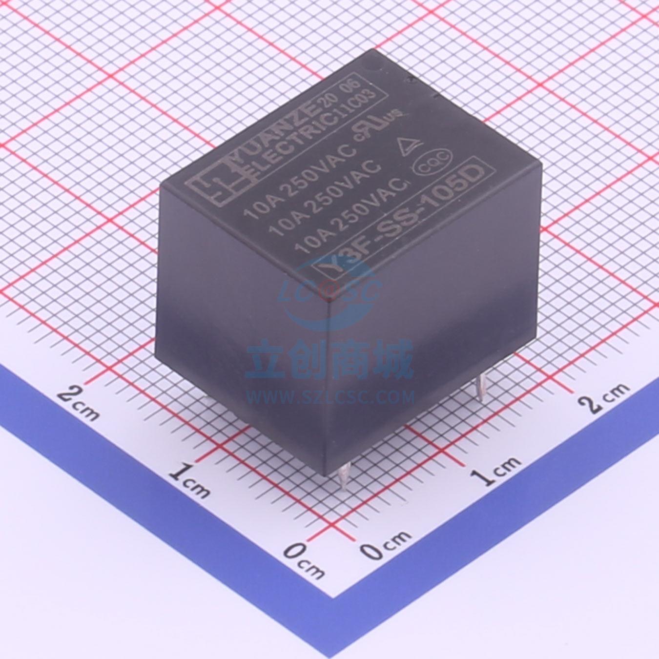 ## The sensor uses Swiss SENSIRION’s [SHTC3](https://item.szlcsc. com/237872.html) Temperature and humidity sensor, I2C communication, 2 x 2 x 0.75 mm3 DFN extremely small package, elegant without losing accuracy, it is the same sensor as Xiaomi Thermohumidity Meter Pro.  ## R! G! B! ~~It is well known that RGB can improve performance by 200%~~ In view of the size of the board and the remaining area, I decided to put 4 WS2812. Anyway, 1.6 million colors, any indicator light is fine, it can also be used as a simulated smart light, and only one IO is needed. It can drive all series LEDs, which is quite elegant. There are also two IO direct drive LEDs, but they are of no use. I just feel uncomfortable looking at the empty IOs! [WS2812E](https://alimg.szlcsc.com/upload/public/product/source/20180907/D21BC36E103CE41725C46F8E80DB4DA2 .jpg) ## Various interface weak points use the [Type-C](https://item.szlcsc.com/177331.html) interface, which fully meets the weak current power supply requirements on the right. At the same time, CH340E can be used to program/update programs. , of course, you can also use the OTA function of ESP8266 to upgrade online, but of course that is a story later.   The 220V part provides two options, one is a screwed [fence terminal](https://item.szlcsc.com/376686.html), and the other is an ordinary plug terminal, details See Lichuang Mall [C395684](https://item.szlcsc.com/376431.html), a more general model, you can choose it by yourself. 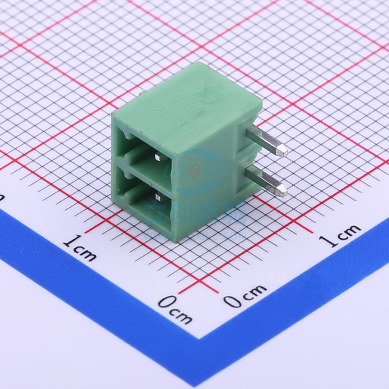 Two solder pads are provided on the back of the board to facilitate the use of power supply other than USB. Next to the USB The diode is used to select the power supply. If USB power supply is used, it does not need to be attached. #Other Notes##### There is no material number silk screen on the PCB. You can use [HTML BOM](http://hfws.hfgzs.xyz/8266-RGZZ-PCB-0.2.0.html) to confirm the component details. Location. [HTML BOM Tutorial](http://club.szlcsc.com/article/details_44132_1.html) Thanks scarrrr!
- - - ##### The second board I tried to use STC+EMW3080 gave up and will probably be deleted. (Already deleted) - - - ##### The copyright of the silk screen on the back belongs to Arknights/Eagle Point Network. Others are not allowed to use this image. Please delete it before printing, otherwise the commercial copyright issues caused have nothing to do with the author. . - - - ##### Thanks to EMZ1 for helping me learn how to display static web pages with my own domain name, allowing me to publish online BOM # Historical update 2020/08/24 00:55 Updated test photos and videos 2020 /08/10 23:50 Change the relay to two-state, add online BOM, delete the unnecessary second board 2020/08/10 21:54 Add description 2020/08/20 21:00 Repair the mains wiring spacing that is too close Bug, thanks to Zhou Gong2020/08/09 Completed PCB drawing 2020/08/08 Completed schematic drawing
# Some current problems are due to the fact that DataSheet was not carefully studied during the design, resulting in some GPIO designs being irregular or unable to operate at full speed, and not all functions have been implemented yet. The I2C part is also due to the fact that I did not understand or consider the design requirements of I2C high-frequency wiring during the design, resulting in SHTC3 being temporarily unusable (in fact, I did not learn how to use it on the development board) and then the dual-channel control, temporarily I haven't written it yet, I just wrote the program to control one relay. # Main functions ### Can be connected to the Internet, can control switches, can sense temperature and humidity, and can also simulate smart RGB lights. Of course, 2812 lights labeled as RGBW are better ### The PCB uses standard credit card size, and the corner holes are suitable for M3 size screws If the column is installed and fixed, you can make a board and come back to see if it is the same size as a meal card or bank card qwq ### You can program the firmware at will, and you can even use it as a development board # Device selection ## Main control ESP8266 module, compatible with ESP12S 12E 12F 07S is compatible with Arduino to develop its own MCU, without the need for additional chip control.  ## The relay uses Yuanze’s Y3F series relay. This project uses [Y3F-SS-105D] (https://item.szlcsc.com/705465.html), it is a single-channel two-state relay with a resistive load capacity of 10A 250VAC. Using two relays to achieve the effect of independent control of dual-channel four-channel switches, it can even be achieved with a motor. Forward and reverse, further expand the function of this switch.  ## The sensor uses Swiss SENSIRION’s [SHTC3](https://item.szlcsc. com/237872.html) Temperature and humidity sensor, I2C communication, 2 x 2 x 0.75 mm3 DFN extremely small package, elegant without losing accuracy, it is the same sensor as Xiaomi Thermohumidity Meter Pro.  ## R! G! B! ~~It is well known that RGB can improve performance by 200%~~ In view of the size of the board and the remaining area, I decided to put 4 WS2812. Anyway, 1.6 million colors, any indicator light is fine, it can also be used as a simulated smart light, and only one IO is needed. It can drive all series LEDs, which is quite elegant. There are also two IO direct drive LEDs, but they are of no use. I just feel uncomfortable looking at the empty IOs! [WS2812E](https://alimg.szlcsc.com/upload/public/product/source/20180907/D21BC36E103CE41725C46F8E80DB4DA2 .jpg) ## Various interface weak points use the [Type-C](https://item.szlcsc.com/177331.html) interface, which fully meets the weak current power supply requirements on the right. At the same time, CH340E can be used to program/update programs. , of course, you can also use the OTA function of ESP8266 to upgrade online, but of course that is a story later.   The 220V part provides two options, one is a screwed [fence terminal](https://item.szlcsc.com/376686.html), and the other is an ordinary plug terminal, details See Lichuang Mall [C395684](https://item.szlcsc.com/376431.html), a more general model, you can choose it by yourself.  Two solder pads are provided on the back of the board to facilitate the use of power supply other than USB. Next to the USB The diode is used to select the power supply. If USB power supply is used, it does not need to be attached. #Other Notes##### There is no material number silk screen on the PCB. You can use [HTML BOM](http://hfws.hfgzs.xyz/8266-RGZZ-PCB-0.2.0.html) to confirm the component details. Location. [HTML BOM Tutorial](http://club.szlcsc.com/article/details_44132_1.html) Thanks scarrrr!
- - - ##### The second board I tried to use STC+EMW3080 gave up and will probably be deleted. (Already deleted) - - - ##### The copyright of the silk screen on the back belongs to Arknights/Eagle Point Network. Others are not allowed to use this image. Please delete it before printing, otherwise the commercial copyright issues caused have nothing to do with the author. . - - - ##### Thanks to EMZ1 for helping me learn how to display static web pages with my own domain name, allowing me to publish online BOM # Historical update 2020/08/24 00:55 Updated test photos and videos 2020 /08/10 23:50 Change the relay to two-state, add online BOM, delete the unnecessary second board 2020/08/10 21:54 Add description 2020/08/20 21:00 Repair the mains wiring spacing that is too close Bug, thanks to Zhou Gong2020/08/09 Completed PCB drawing 2020/08/08 Completed schematic drawing

All reference designs on this site are sourced from major semiconductor manufacturers or collected online for learning and research. The copyright belongs to the semiconductor manufacturer or the original author. If you believe that the reference design of this site infringes upon your relevant rights and interests, please send us a rights notice. As a neutral platform service provider, we will take measures to delete the relevant content in accordance with relevant laws after receiving the relevant notice from the rights holder. Please send relevant notifications to email: bbs_service@eeworld.com.cn.
It is your responsibility to test the circuit yourself and determine its suitability for you. EEWorld will not be liable for direct, indirect, special, incidental, consequential or punitive damages arising from any cause or anything connected to any reference design used.
Supported by EEWorld Datasheet
EEWorld
subscription
account

EEWorld
service
account

Automotive
development
community

Robot
development
community

About Us Customer Service Contact Information Datasheet Sitemap LatestNews


Room 1530, 15th Floor, Building B,
No.18 Zhongguancun Street,
Haidian District,
Beijing, Postal Code: 100190
China
Telephone: 008610 8235 0740
 京公网安备 11010802033920号

 JE12B48HTB1


