The information outline has been planned and will be updated one after another...
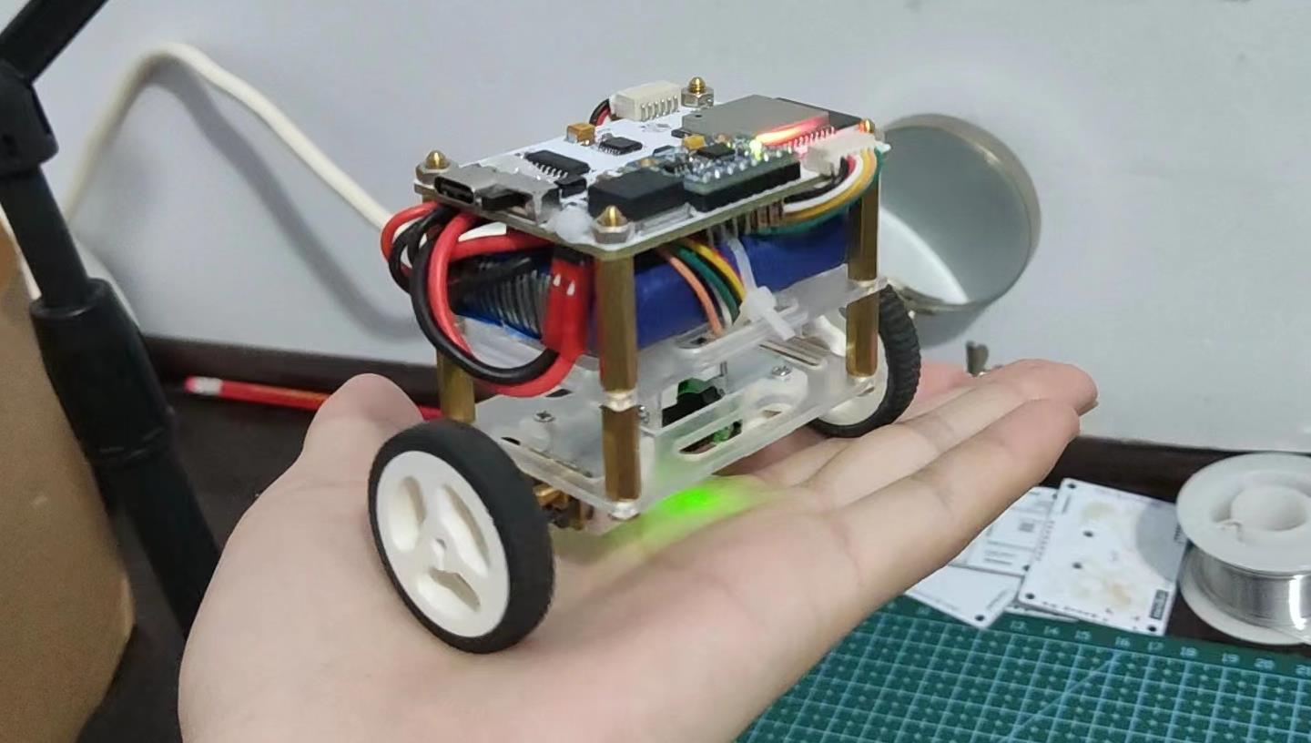
The balancing car is a must-do item for almost everyone who is into electronic DIY. It covers many fields such as sensor acquisition and processing, motor motion control, pid algorithm adjustment, etc. It is professional and interesting at the same time, and is very suitable as an introductory exercise project. After several version iterations (see subsequent introduction), this project was finally determined in its current form, which has achieved a good balance in appearance structure and software control, with a compact appearance and excellent sports performance.
Special Note:
ESP32-WROOM is used as the main control chip, and the MPU6050 six-axis acceleration sensor module obtains attitude information. The DRV8833 chip drives the motor movement and provides a large current. The motor uses an N20 reduction motor with an AB phase Hall encoder for measuring rotational speed. For power supply, a 7.4V lithium battery (2s) is used. The linear voltage regulator LM1084 is used to stabilize the voltage to 5V, and then the LM1117 is used to stabilize the voltage to 3.3V to power the ESP32.
The program is partially based on the Arduino IDE, using an open source library to achieve angle acquisition and pid algorithm balance control, using a JSON library to write an instruction parsing program for Bluetooth remote adjustment of pid parameters, and using the open source Android Bluetooth APP to remotely control the movement of the car.
B station demonstration video: [Homemade] Super mini handheld balancing car, with Bluetooth pid parameter adjustment and remote control_bilibili_bilibili
Open Source Platform: minibot - Jialichuang EDA open source hardware platform (oshwhub.com)
First edition:
Related demonstration video: The balance car that has just adjusted the angle and ring pid is not yet stable_bilibili_bilibili
second edition:
The final effect is shown in the picture below. Click here for the demonstration video: The second round of the balancing car - the trembling Bingdundun_bilibili_bilibili
----------------------------Dividing line-------------------- ----------------
Below are the design notes for the current final version, version 3.
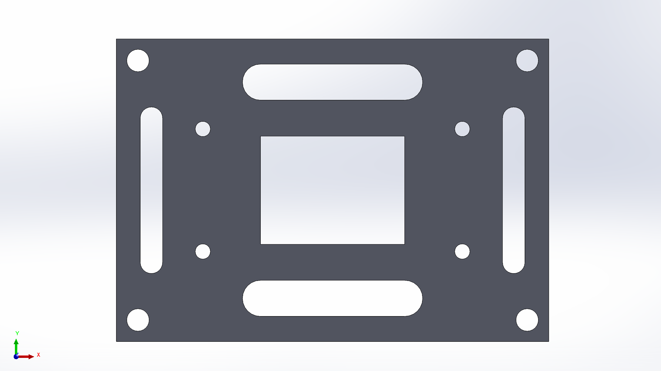
Complete structural modeling : The original plan was to use two-layer boards stacked (such as the first version), with the battery placed in the middle. However, the motor cable needs to protrude upward, and the battery cannot be placed underneath, so an additional layer is added and a three-layer board is used. Stacked structure, the lower two layers are cut from acrylic, the uppermost layer is the circuit board, the battery is placed on the upper layer, and the lower layer is hollowed out to lead out the motor cable. The acrylic board also needs to add holes for the motor fixing frame, and arrange the motors as close as possible to reduce the Horizontal spacing. solidworks modeling is as follows:
In addition to the circuit board, there are only two identical acrylic boards that need to be customized, which can be customized by exporting them as DWG files from solidworks.
Power supply : powered by a 2s battery with a nominal voltage of 7.4V, and the access point is set to switch on and off. The main control power supply is 3.3V, and the battery needs to be stepped down twice. In order to simplify the circuit, a low dropout linear regulator (LDO) is used. The first stage uses LM1084 to step down to 5V, and the second stage uses AMS1117 to step down to 3.3V.
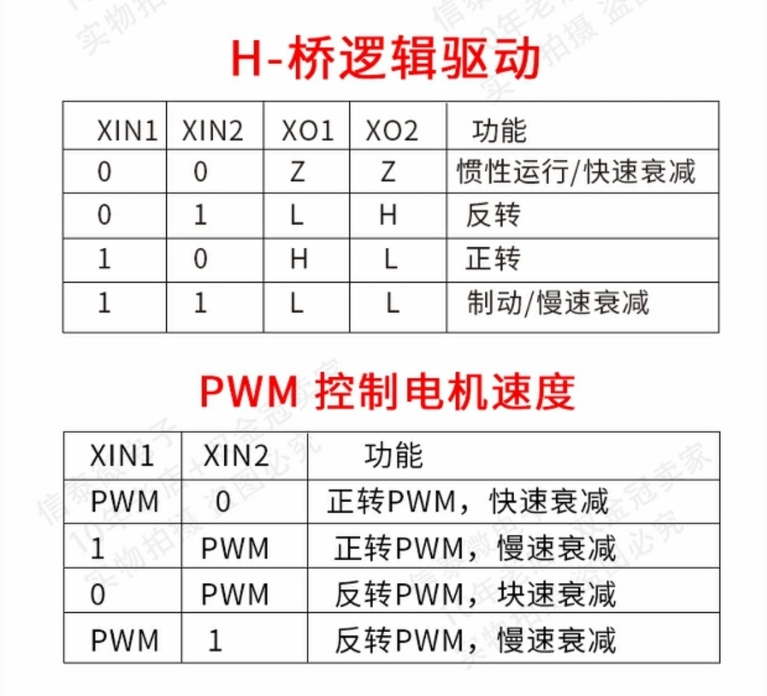
Motor drive : The driver chip uses DRV8833, which is relatively cheap. Although the drive current is not too large, it is enough to drive the N20 motor. One chip can drive two motors. The function table is as follows. Each motor requires two PWM inputs for speed regulation. The two motors have a total of four PWM inputs.
Serial port download circuit : Type-C + CH340C realizes serial port communication, and the conventional double triode circuit realizes automatic downloading.
MPU6050 circuit : Use the module directly and connect four wires (power, ground, and two signal wires) to read data normally.
Please see the engineering schematic for the rest of the circuit details, which have been heavily annotated.
Component layout : Layout according to the main signal flow direction, mainly the power supply part needs to be concentrated to facilitate wiring. Some small devices are also placed in the blank space below the MPU6050 module, giving it a sense of 3D circuitry.
Manual wiring : The wiring is only usable, and there is still a lot of room for improvement. Then pay a little attention to the line width. The power supply part should be as wide as possible, and the signal line can be narrower.
My level of circuit design is limited. You are welcome to provide valuable opinions and learn and make progress together. Thank you.
During the circuit board welding test,
the CH340 was missing a capacitor (see the debug section). This version temporarily solved the problem by flying wires, and then fixed it with a piece of hot melt glue. Hot melt adhesive is also added to the power interface to prevent short circuits.
Overall assembly:
The lower two layers of acrylic board and the upper layer of PCB are connected and fixed with M3 hexagonal copper posts. The length can be as short as possible, but a certain amount of space is required for the battery and cables. The length used at the bottom is 15mm, and the length at the top is 20mm. The bottom motor uses the supplied motor base and is fixed with screws.
The CH340 V3 interface lacks a 0.1uF capacitor for grounding, which prevents normal connection to the serial port. The current version can work normally after connecting the capacitor with flying wires. The PCB has been repaired in the v1.1 version.
The direction of the motor cable 6p socket is set in the wrong direction. The original design was to place it on the back, but according to the actual wiring sequence, it needs to be placed on the front . It has been marked in the v1,.1 version. Please pay attention to check, otherwise it may easily cause the risk of short circuit .
Todo
Main components:
| name | quantity | unit price | illustrate | Link |
|---|---|---|---|---|
| ESP32-WROOM | 1 | 12.3 | Select model ESP-WROOM-32 | Order link |
| MPU6050 | 1 | 6 | Commonly used modules, the basic ones from other sources are also common. | Order link |
| DRV8833 | 1 | 2.5 | I chose the drv8833 module. The module is cheaper than the chip, so I chose to buy the module and remove the chip. | Order link |
| N20 motor | 2 | 25 | The model selected is 6V-310 rpm | Order link |
| 7.4V battery | 1 | 34.5 | 2s battery, choose 700 mAh JST interface (you also need to prepare a 2P pin header as a socket), it is best to buy a charger yourself | Order link |
| M3 copper pillar | 8 | 7.8(total 20) | There are two options: M3 *15 and M3 *20 | Order link |
| M3 nut | 4 | 1.5(total 100) | Buy it from the Tongzhu store above (Uxin Electronics), search M3 and you’ll find it | -- |
| ZH1.5-6P female base | 2 | 2.4(total 10) | Choose a 6P curved needle (later I found that a straight needle is more beautiful, but you need to pay attention to the polarity when welding) | Order link |
| ZH1.5-6P double-ended cable | 2 | 4.2(5 in total) | Choose 6P double head, any length | Order link |
| Toggle Switches | 1 | 2(total 20) | For the model, choose SK12D07VG4 toggle switch with 2 positions and 3 pins. There are several similar ones. Be careful not to choose the wrong one. | Order link |
| Acrylic board | 2 | -- | Customize by yourself, see the attachment for customization files模型装配/亚克力切割.DWG |
-- |
Other components: The remaining components such as CH340, AMS1117, resistors and capacitors are relatively conventional. They can be ordered according to the BOM table. You can place an order directly with Lichuang or buy them one by one from a certain store. Pay attention to the package model when buying.
The model files have been uploaded to the attachment, including the complete solidworks modeling assembly file. The car is modeled according to the actual size, which can provide some reference. For acrylic board cutting, use the DWG file inside, put two identical boards, and just customize it directly.
Please open the circuit diagram part directly from the Lichuang EDA project file at the end. The attachment will not be included. A large number of comments have been added to the schematic diagram for reference.
See the attached code. It is currently the latest version. Subsequent optimization will be marked with the version number and uploaded. When developing using Arduino IDE, the libraries that need to be downloaded and prepared by yourself include <ArduinoJson.h> and <MPU6050_tockn.h>. Each module in the project is a combination of .h+.cpp files, and a lot of comments have been added, which you can check by yourself.
Bluetooth parameter adjustment: You need to change the BTMODE macro definition at the beginning to 0 (the default is 1, which is remote control mode). The mobile APP can use any Bluetooth debugging APP. For the sending command format, see the comments in the code:
/* 蓝牙发送参数指令,使用JSON格式进行打包和解析,字符串格式:"{"cmd":1,"data":[p,i,d]}" ,  (p、i、d为常数)
 * cmd=1:角度环pid设置
 * cmd=2:速度环pid设置
 * cmd=3:转向环pid(暂未添加)
 * cmd=4:角度平衡值, 发送格式: "{"cmd":4,"data":[angle]}" , (angle为常数)
 * cmd=5:速度值,同角度
 * cmd=6:转向值,同上
**/
Bluetooth remote control: The APP for remote control is included in the attachment, and is only available on the Android platform. The rocker parameters configured in the APP are as shown below:
Structural level: At present, the miniaturization level has almost reached the limit (motor size limit). If it needs to be reduced further, it will have to be replaced with a smaller motor. From the appearance point of view, the biggest problem now is the battery wiring. Most of it is exposed to the outside, which reduces the aesthetics. At the same time, the motor cable is also relatively prominent. If it hits the cable when falling to the ground, it may cause damage. Consider replacing the connector with a straight pin. This can be solved by replacing the current curved needle.
Software level: In the first minute of PID operation, there will be obvious lag and overshoot in the motor movement. It will take a period of time to return to the normal balance mode. The reason has not been found yet. It is estimated to be a problem during the initialization of some variables. It is still being investigated. middle. There is still room for improvement in the stability of the car's operation. It is not very stable when stationary. On the one hand, the PID algorithm and parameters can be optimized. On the other hand, it may be affected by the encoder resolution. According to the 20Hz sampling rate, the encoder data range is 0 Integer values around -50 have very limited data accuracy.

All reference designs on this site are sourced from major semiconductor manufacturers or collected online for learning and research. The copyright belongs to the semiconductor manufacturer or the original author. If you believe that the reference design of this site infringes upon your relevant rights and interests, please send us a rights notice. As a neutral platform service provider, we will take measures to delete the relevant content in accordance with relevant laws after receiving the relevant notice from the rights holder. Please send relevant notifications to email: bbs_service@eeworld.com.cn.
It is your responsibility to test the circuit yourself and determine its suitability for you. EEWorld will not be liable for direct, indirect, special, incidental, consequential or punitive damages arising from any cause or anything connected to any reference design used.
Supported by EEWorld Datasheet
EEWorld
subscription
account

EEWorld
service
account

Automotive
development
community

Robot
development
community

About Us Customer Service Contact Information Datasheet Sitemap LatestNews


Room 1530, 15th Floor, Building B,
No.18 Zhongguancun Street,
Haidian District,
Beijing, Postal Code: 100190
China
Telephone: 008610 8235 0740
 京公网安备 11010802033920号


 CTMD3P-5O1SAU1500


