Project Product Upgrade Announcement: This project has been officially upgraded from the original third-generation unit to the fourth-generation unit. New functions have been added to the foundation of the third-generation unit, making it even more practical!
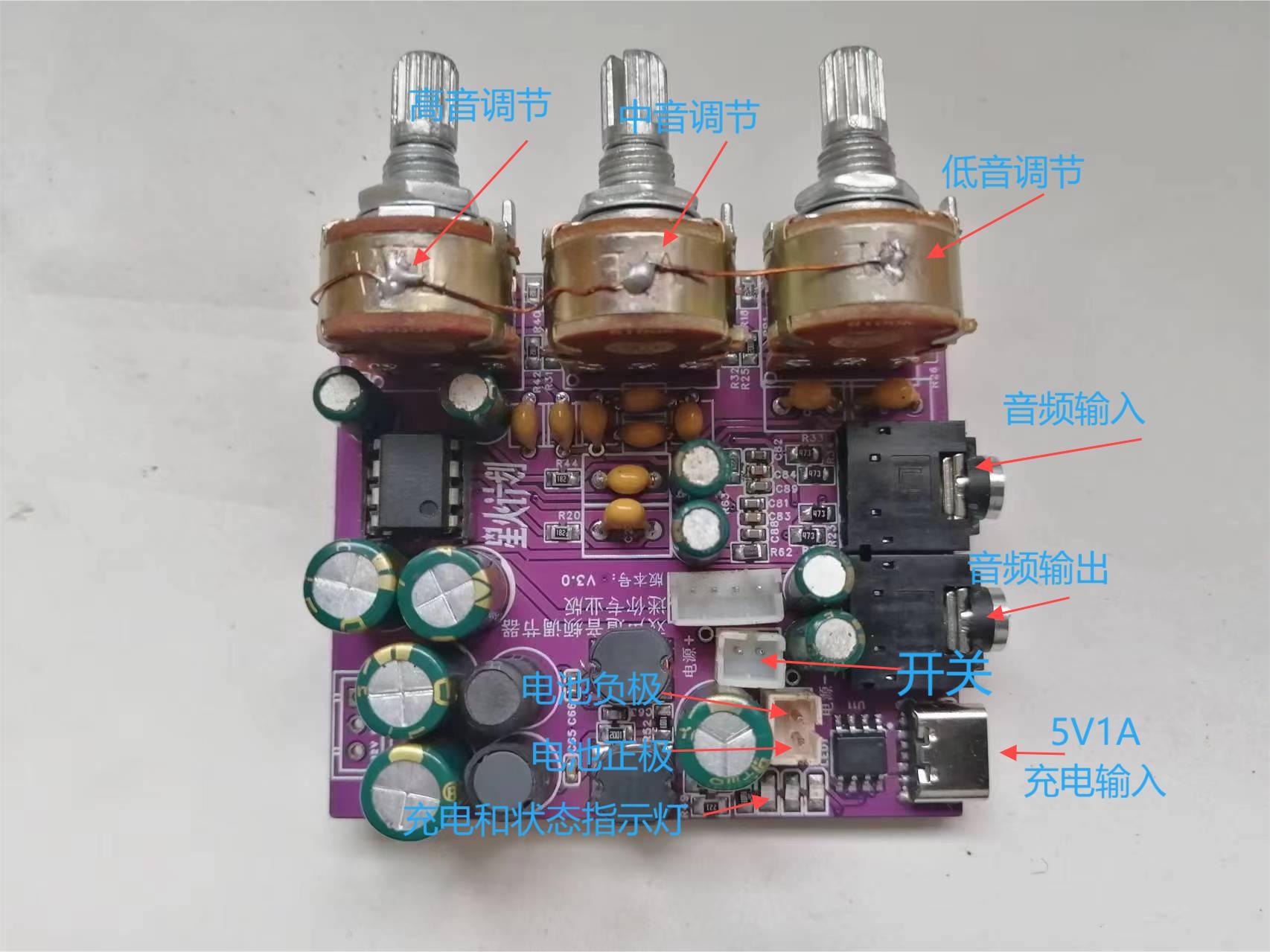
Third-generation unit function overview: Miniature design, easy to carry, independent adjustment of high, mid, and low frequencies, supports Bluetooth audio input, and powered by a built-in lithium battery.
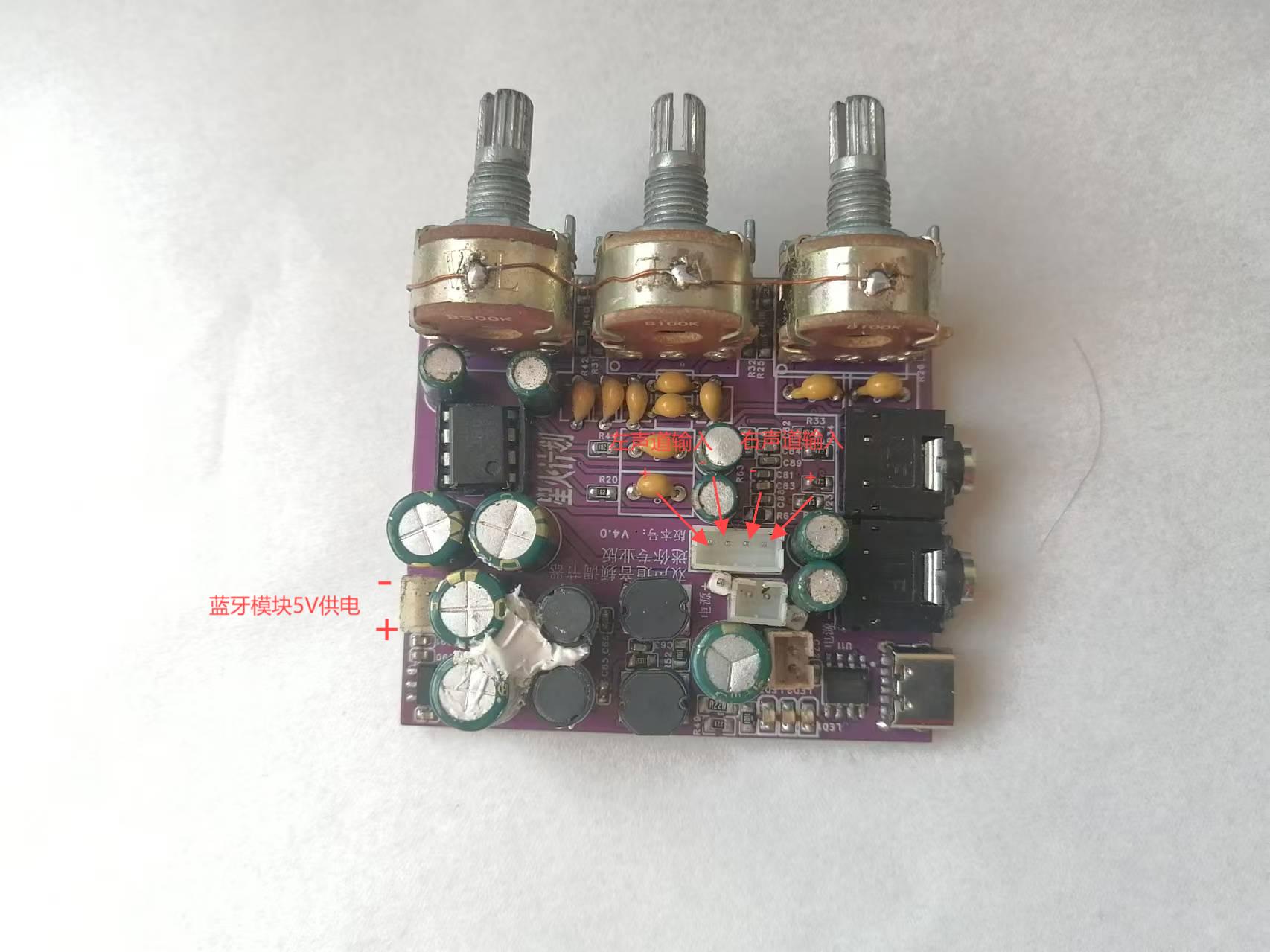
Fourth-generation unit function overview: Possesses all the functions of the third-generation unit, adds a power switching function, can be used plugged in (and even works without batteries), and optimizes the Bluetooth module power supply circuit to ensure stable power supply.
Below is a brief introduction to the third-generation unit:
Currently, music software requires memberships to improve sound quality, and even with memberships, the effect is often unsatisfactory. Purchasing professional tuners is not only expensive but also complex to use. Some devices are bulky, taking up a lot of space and difficult to adjust; others, while small, require connection to a computer and specific software for adjustment. To address this, I specifically designed a multi-purpose portable audio tuner. It can be powered by either Type-C or a built-in lithium battery, making wiring extremely simple. Both audio input and output use 3.5mm headphone jacks. It can be used for adjusting active speaker preamps, subwoofer preamps, or wired headphones for headphone sound quality adjustment. An internal audio input interface is provided, allowing for the addition of a Bluetooth audio receiver module or other modules to expand functionality.
Product features: Small size, portable, easy wiring and adjustment. Rechargeable design, usable as a headphone amplifier. Bluetooth receiver modules can be added as needed to modify ordinary active speakers or subwoofers for Bluetooth functionality.
Ultra-low noise floor, clear and non-harsh treble, transparent and clear bass.
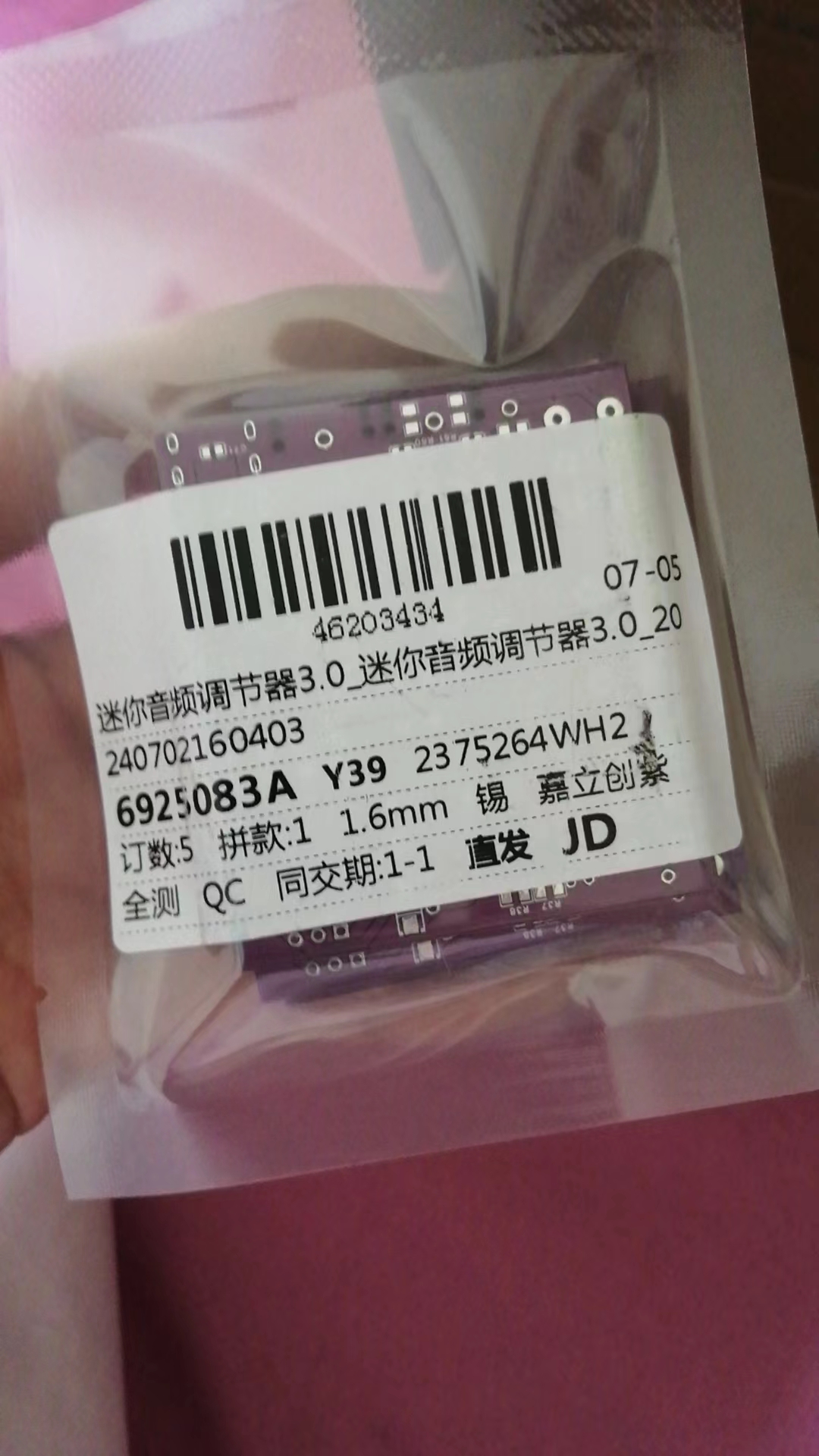
Low project replication cost; as long as the components are in good working order, it can be used directly after assembly without debugging. No microcontroller required, no code download needed.
Low no-load power consumption, ultra-long standby time; actual usage time depends on battery capacity. A battery of 1800mAh or higher is recommended.
Supports battery power or external power supply (external power supply requires shorting RJ1, and both functions cannot be used simultaneously).
Assembly process:
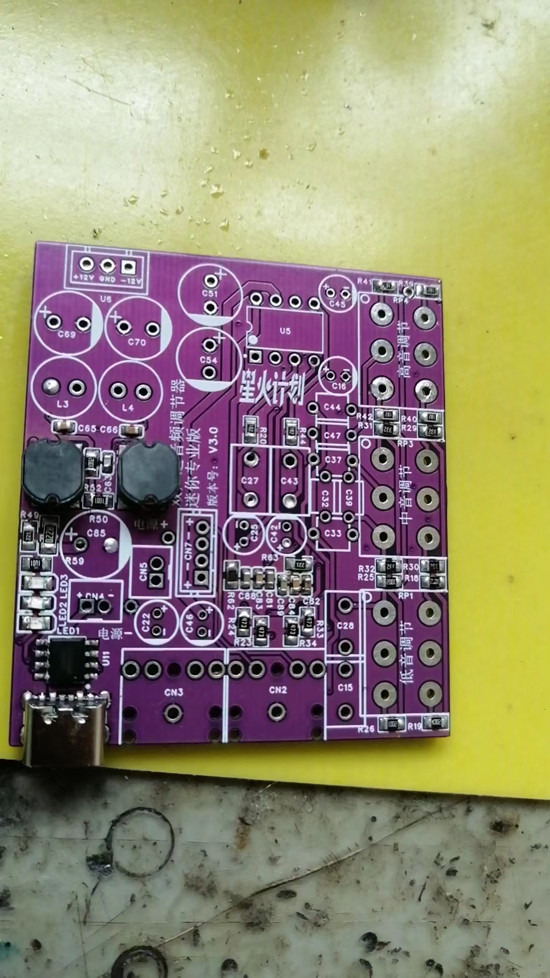

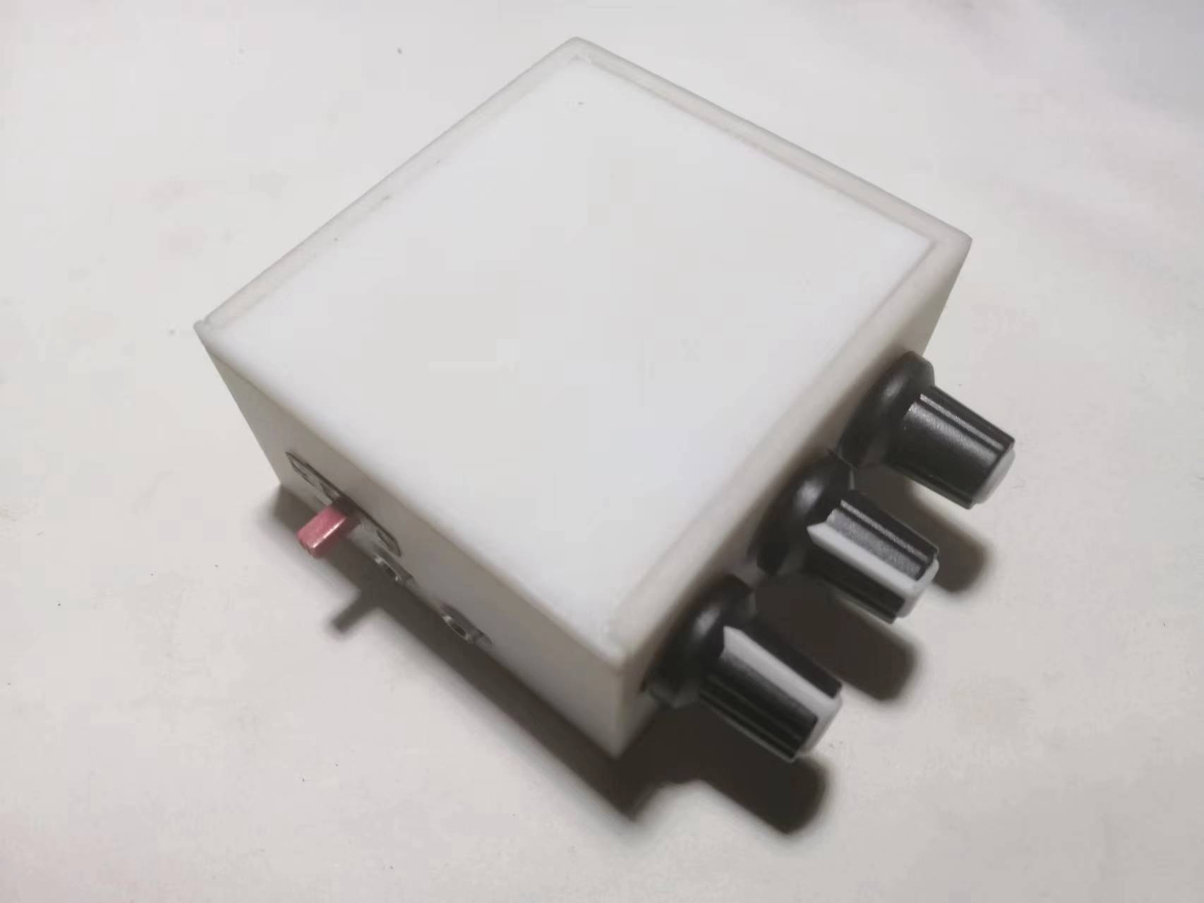
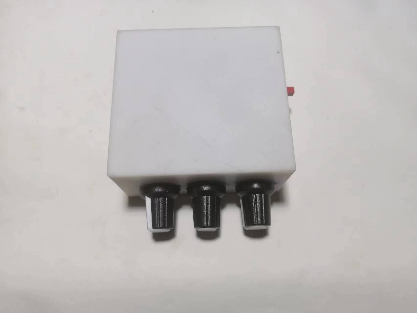
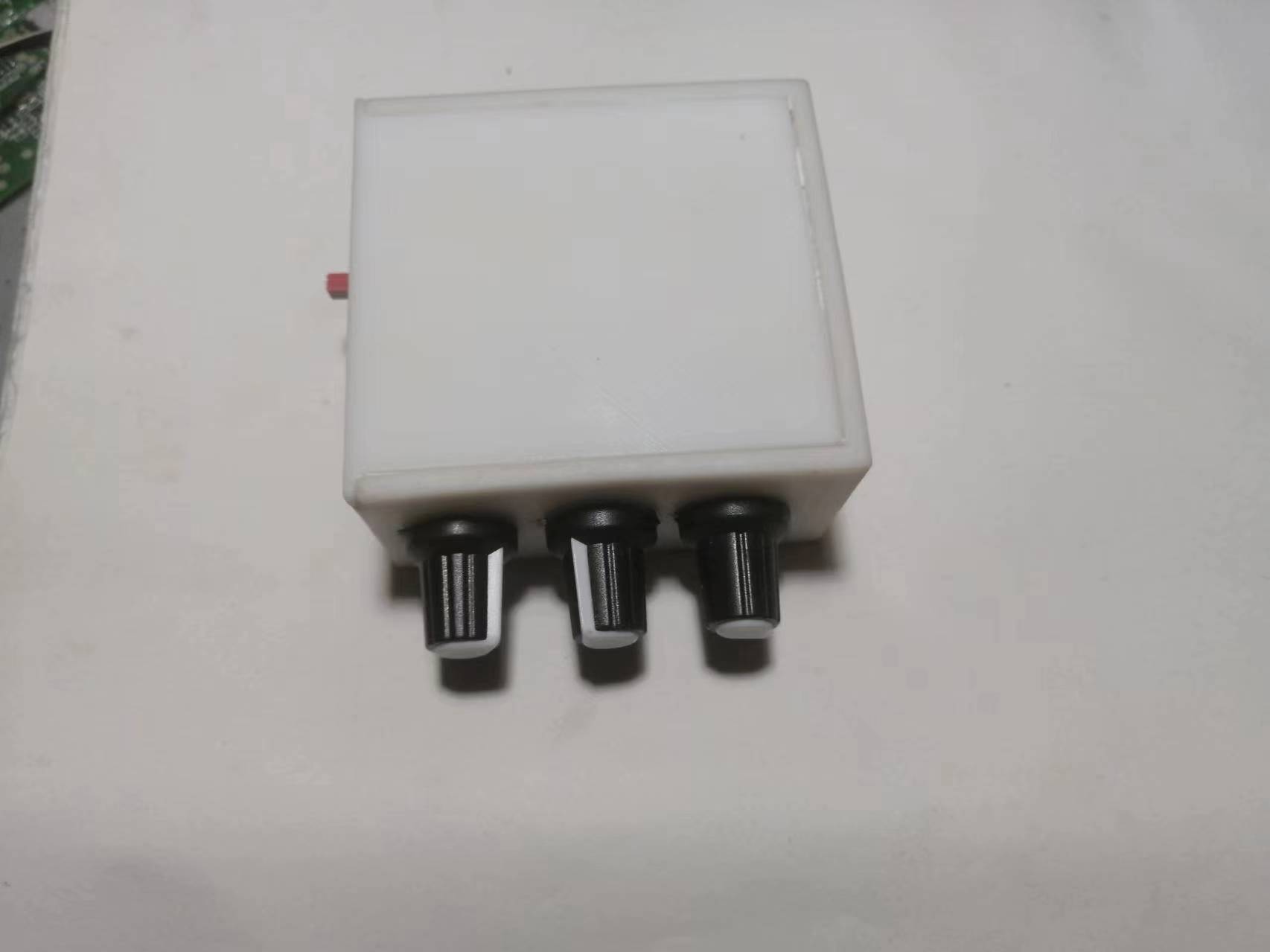
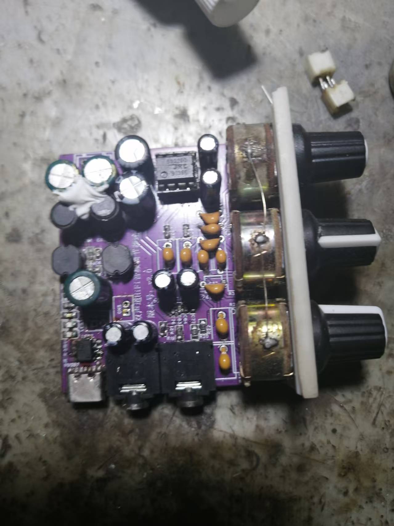
Finished product display


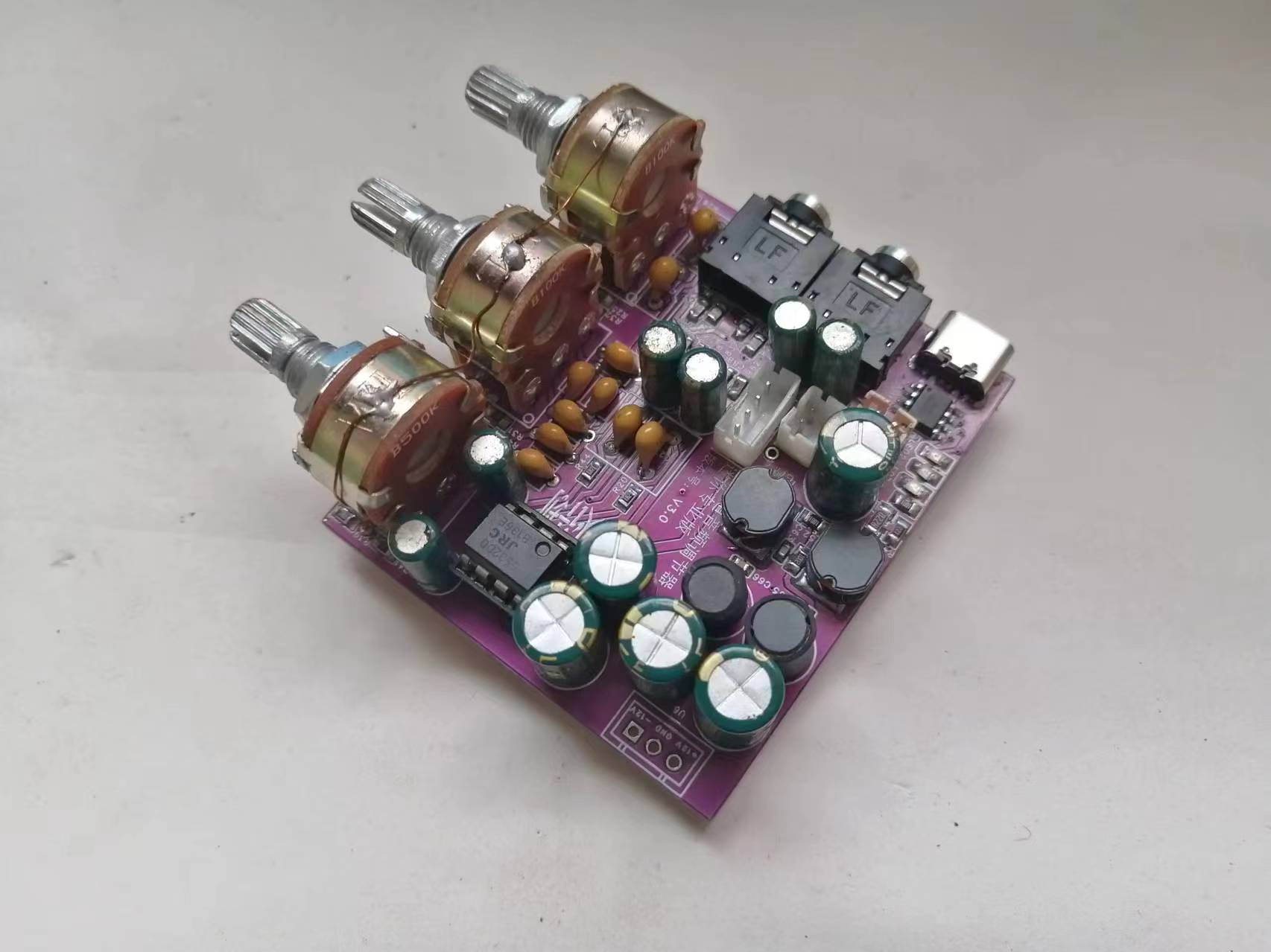

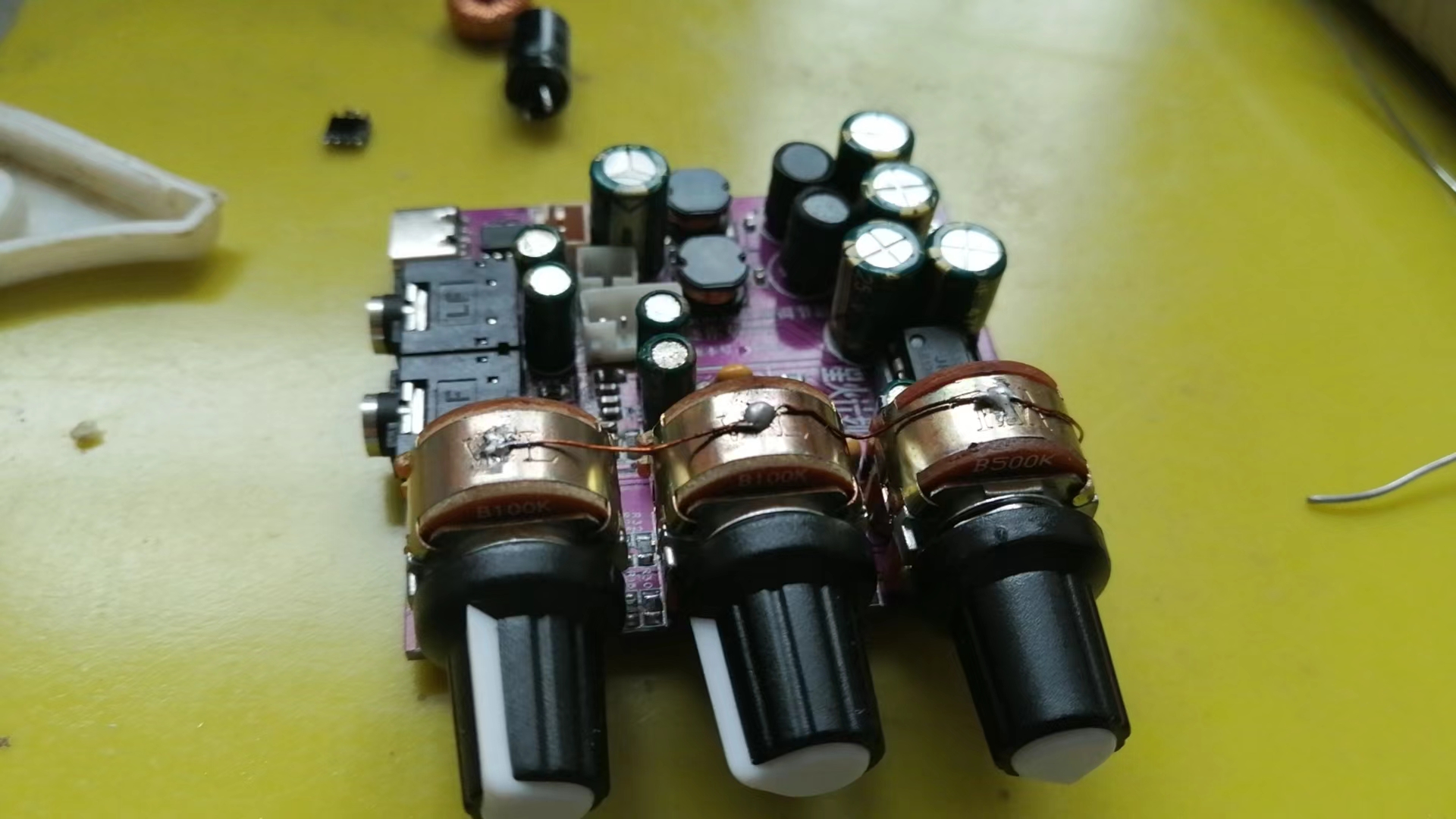
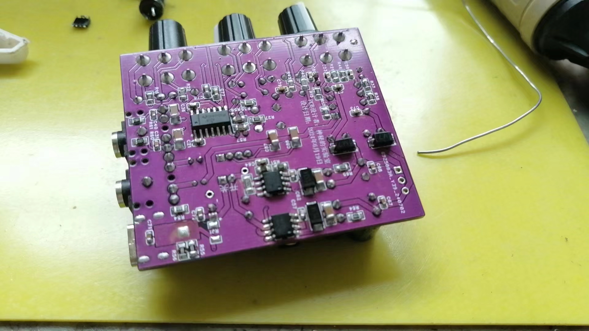
. This project recommends manual soldering, not SMT. The potentiometer casing must be grounded, otherwise there will be background noise.
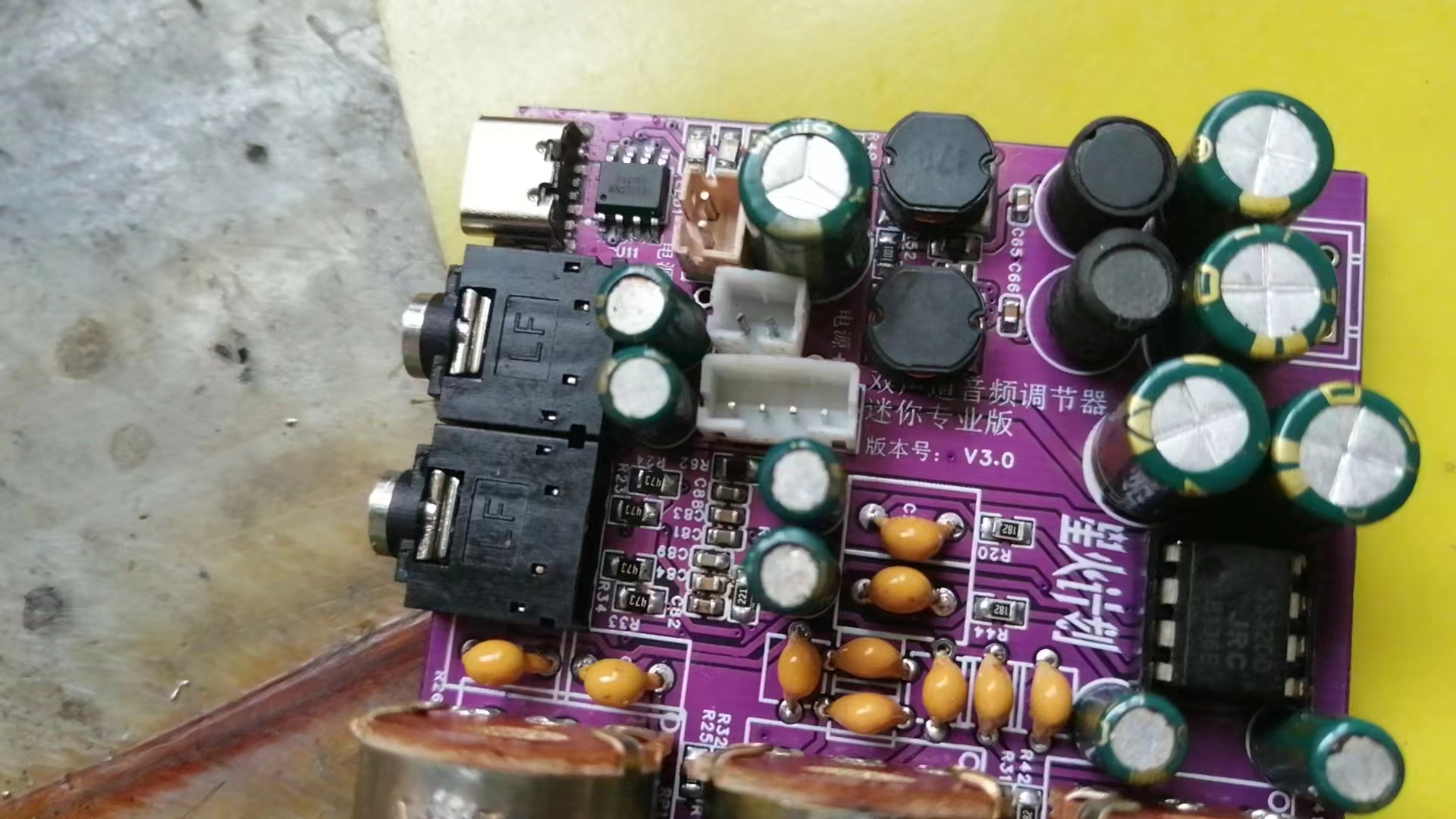
Here is the PCB soldering sequence: First, solder all surface mount components, including surface mount inductors and Type-C charging sockets. Be careful not to get solder into the pads of through-hole components. If the pads are blocked, clean them thoroughly. Then clean the PCB. Note that it must be cleaned very thoroughly. Because once the potentiometer is soldered, the front cannot be cleaned, otherwise the cleaning fluid will flow into the potentiometer and cause damage.
Then solder all through-hole components. After soldering, clean the back of the circuit board as well.
Finally, install the potentiometer. Note that when cleaning the circuit board at this time, be careful not to let the cleaning fluid flow into the potentiometer!!!
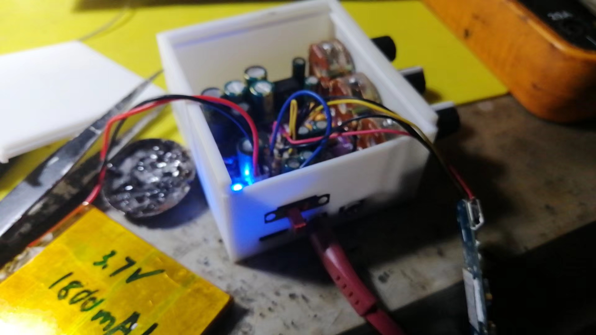
Then you can power it on for testing. First, test whether the charging circuit is working properly. If it is working properly, the charging indicator light should change normally. Then power on and measure whether the dual 12V is normal. Finally, do not connect anything to the audio input terminal, and connect a pair of headphones or speakers to the audio output to listen for background noise.
Troubleshooting charging circuit malfunctions: Check for cold solder joints on the charging socket. If an RJ1 component is soldered, remove it. If the problem persists after replacing the battery, replace the charging chip and test again until the charging circuit works normally.
Troubleshooting dual 12V circuit malfunctions: If the voltage exceeds 14V, focus on checking the feedback circuit. If there is no boost or -12V, focus on checking the boost inductor and diode, and for short circuits in the dual 12V circuit. It is recommended to directly replace the boost inductors (L1, L2). If the problem persists, it is recommended to replace the chip or check if the filter inductors (L3, L4) are open.
Troubleshooting excessive background noise: Remove capacitor C57, reduce the capacitance of C63, and replace C64 with a 4.7nF capacitor.
Troubleshooting poor -12V load capacity: Reduce the resistance of R48 or replace it with a 0Ω resistor.
This circuit does not include a Bluetooth module. To expand Bluetooth functionality, you need to purchase a Bluetooth module separately, and it is essential to purchase a low-noise module. This is because the audio output of the Bluetooth module will affect the overall noise level of the device.
For the 5532DD, if you can't find an original Taiwanese-made one, buy an imported one, as this chip directly determines the final output sound quality.
Below is the wiring diagram and function description.

If you don't like the Bluetooth module, you can add other smart voice modules to achieve more functions.
For the 3D shell, the potentiometer adjustment knob needs to be manually measured for the opening, or you can calculate and reserve the opening yourself during 3D printing.
Below is a brief introduction to the fourth-generation model .
In addition to the original functions of the third-generation model, the fourth-generation model has optimized the power supply circuit, allowing it to be used plugged in without interfering with battery charging.
Below is a brief introduction to some of the improved interfaces of the fourth-generation model .


By the way, I'll also show the previous second-generation model (which is now obsolete).
Here I'm using a ready-made Bluetooth module; you can also use a salvaged Bluetooth headset.


Below is what the wires look like. If you don't need the buttons, you can leave them unconnected. Similarly, if there is too much noise, you can connect a capacitor of about 4700uF in parallel at the input of the Bluetooth module to solve the problem.

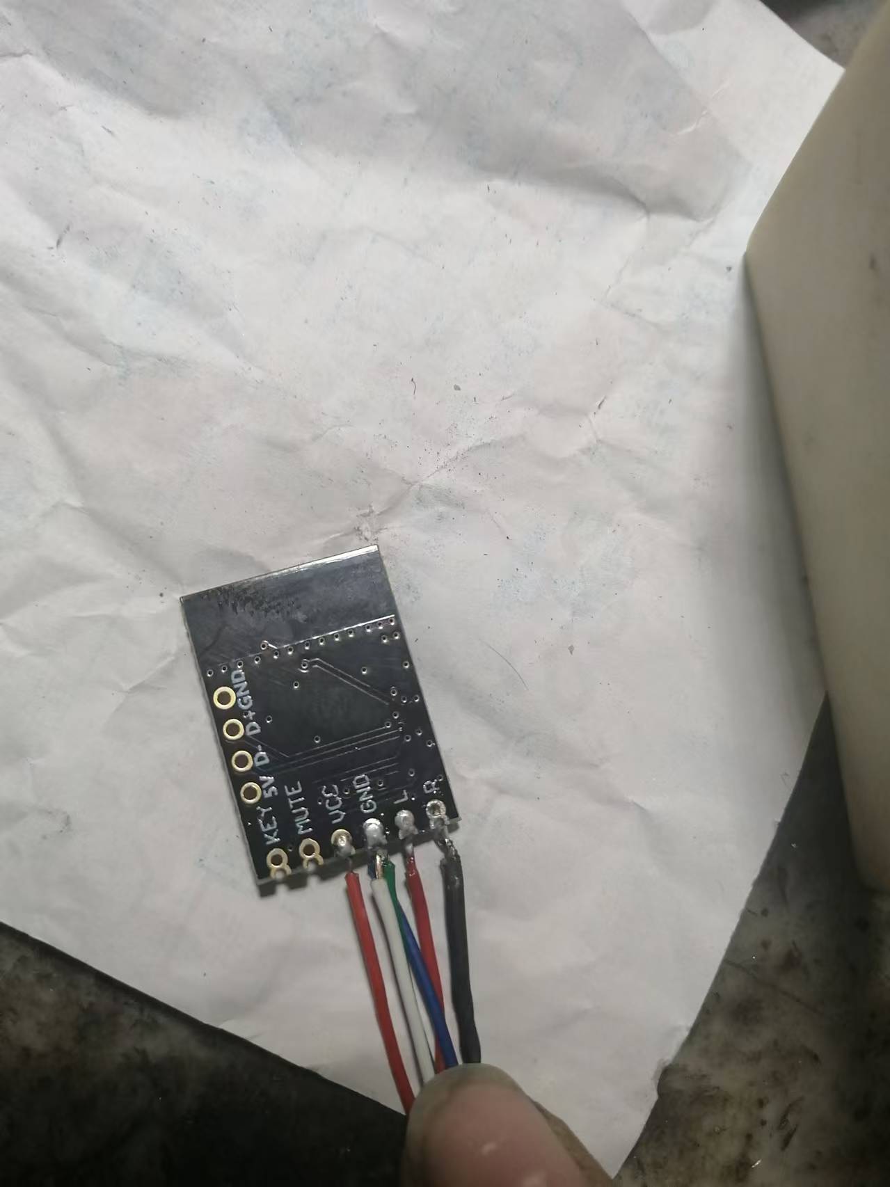
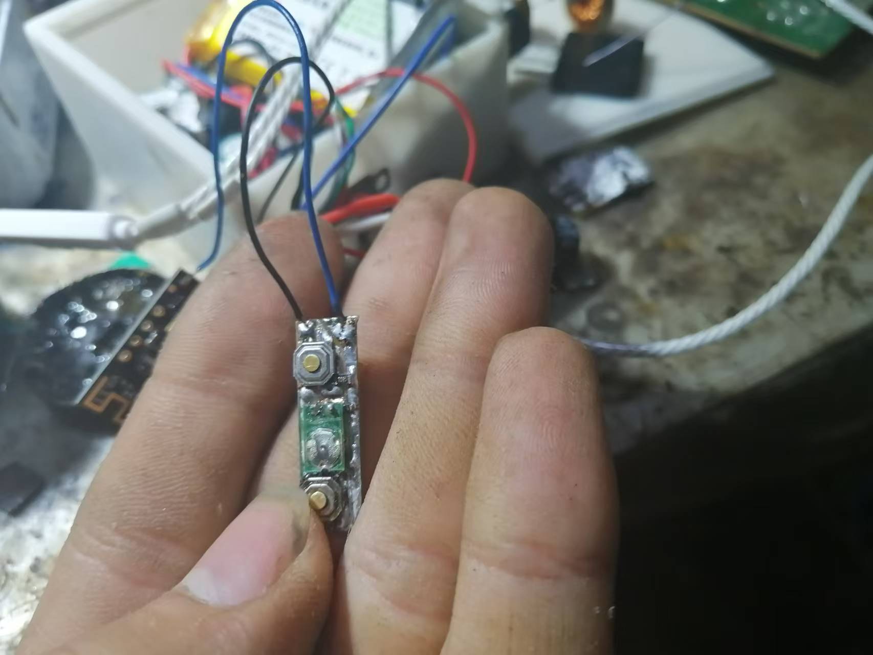
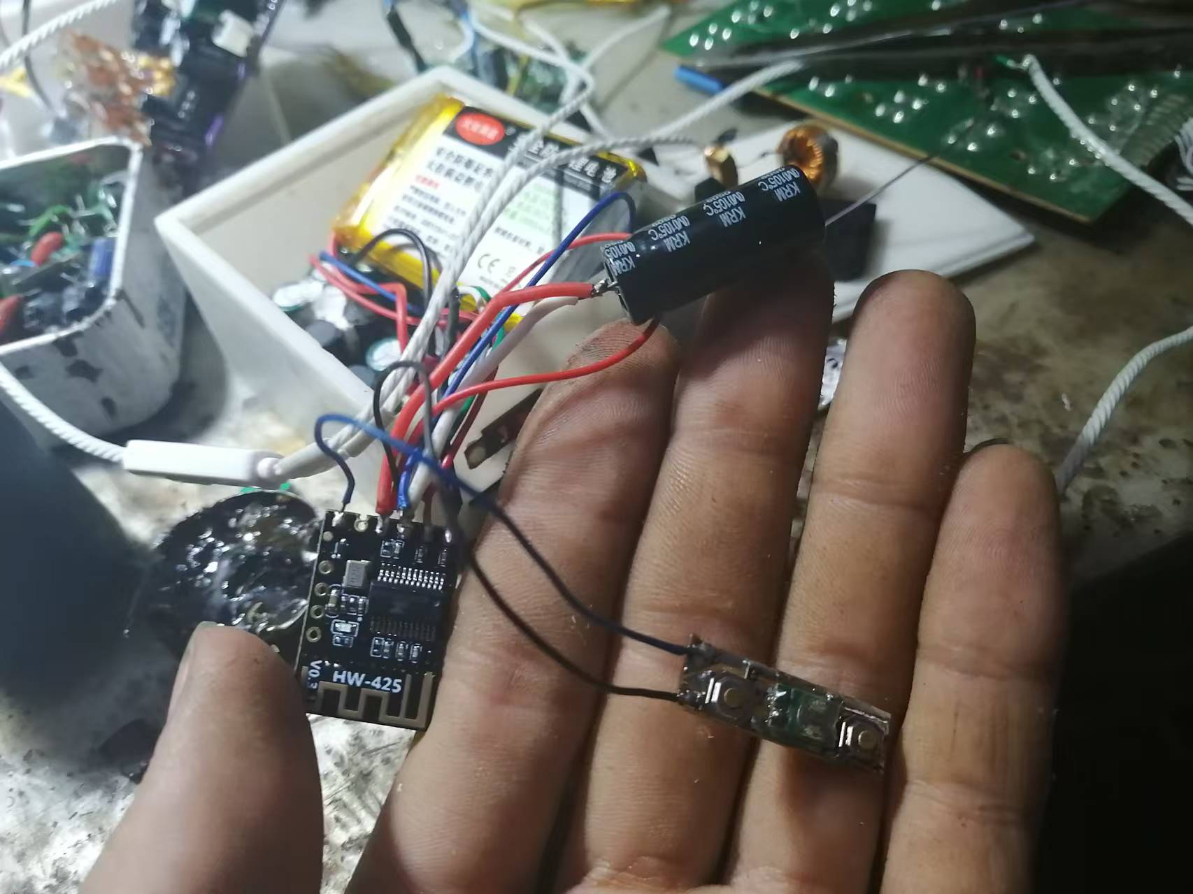
As for how to wire the Bluetooth module, just ask the seller for the wiring diagram.
Below is the link to the test video (Bilibili link):
https://www.bilibili.com/video/BV1vvmyYyEr9?t=39.3
In addition, the 3D shell uses the shell from the third-generation model, as shells are universal.
Finally, happy DIY everyone!


 京公网安备 11010802033920号

 EYC60DRAN


