Github open source: https://github.com/Nuozhihui/Velocity_measurement
The STC51 microcontroller is used as the main control , and the pulse signal is generated through the photoelectric tube for shaping processing through the LM393 inverter. Use interrupts to detect speed. Used to measure lathe speed and trolley speed measurement.
This project is used to verify the solution verification board design of Lichuang Mall LM393 (Mall No. C400839 )
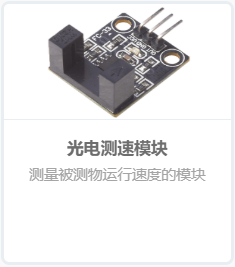
This photoelectric slot type optocoupler sensor is an infrared sensor based on the infrared tube module. The sensor module has strong adaptability to ambient light. It has a pair of infrared transmitting and receiving tubes. The transmitting tube emits infrared rays of a certain frequency. When an obstacle (reflective surface) is encountered in the detection direction, the infrared rays are reflected back and received by the receiving tube. After processing by the comparator circuit, the indicator light will light up, and at the same time the signal output interface outputs a digital signal (a low-level signal). This sensor is widely used for motor speed detection, pulse counting, position limit, etc.
1. Module parameter description
(1) There is an output status indicator light. When the output level is high, the light is off, and when the output level is low, the light is on.
(2) If there is occlusion, the output will be high level; if there is no occlusion, the output will be low level.
(3) Comparator output, clean signal, good waveform, strong driving ability, exceeding 15mA.
(4) Working voltage 3.3V-5V
(5) Output form: digital switching output (0 and 1)
(6) Using wide voltage LM393 comparator
2. Module interface description
(1) VCC power supply positive
(2) GND power supply negative
(3) DO digital output
(4) AO invalid
photoelectric slot type optocoupler module internal circuit diagram is shown in the figure below, in which the R1 resistor is a voltage dividing resistor, which converts the obstacle information detected by the photoelectric slot type optocoupler sensor into an analog voltage signal , after the analog signal is connected to the LM393 comparator, it can be compared with the analog voltage divided by the voltage dividing resistor connected to pin 2 of the LM393 comparator chip, and then the DO digital signal (ie, high and low level signals) can be obtained . C1 and C2 are filter capacitors, and C1 capacitor filters the power supply to make the power output more stable. The C2 capacitor filters the analog signal to ensure the stability of the analog signal output. R2 and R3 are both current-limiting resistors to protect the LED lights and prevent them from burning out. The LED lights are all active at low level. R7 is also a current-limiting resistor to protect the infrared transmitter from burning out. R4 is a pull-up resistor. The pull-up clamps the uncertain signal to a high level through a resistor and also acts as a current limiter. Ensure that the high and low level signals output by the LM393 comparator can be read more stably when connected to the microcontroller pins.

All reference designs on this site are sourced from major semiconductor manufacturers or collected online for learning and research. The copyright belongs to the semiconductor manufacturer or the original author. If you believe that the reference design of this site infringes upon your relevant rights and interests, please send us a rights notice. As a neutral platform service provider, we will take measures to delete the relevant content in accordance with relevant laws after receiving the relevant notice from the rights holder. Please send relevant notifications to email: bbs_service@eeworld.com.cn.
It is your responsibility to test the circuit yourself and determine its suitability for you. EEWorld will not be liable for direct, indirect, special, incidental, consequential or punitive damages arising from any cause or anything connected to any reference design used.
Supported by EEWorld Datasheet
EEWorld
subscription
account

EEWorld
service
account

Automotive
development
community

Robot
development
community

About Us Customer Service Contact Information Datasheet Sitemap LatestNews


Room 1530, 15th Floor, Building B,
No.18 Zhongguancun Street,
Haidian District,
Beijing, Postal Code: 100190
China
Telephone: 008610 8235 0740
 京公网安备 11010802033920号


 MI-P7LJ-IYY